


Rev. A
Multi Pro 5700–D
Page 6 – 40
Spray System
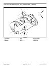
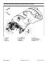
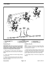
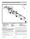
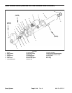
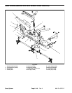
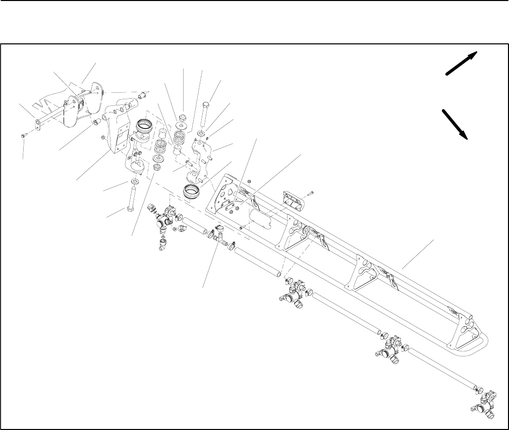
Boom Hinge (Machines with Serial Numbers Above 260000000)
1. Hinge (2 used per boom)
2. Rubber boot (2 used per hinge)
3. Backing plate (4 used per hinge)
4. Flange nut (4 used per hinge)
5. Boom (RH shown)
6. Tee fitting
7. Flange hd screw (4 used per hinge)
8. Lock nut
9. Cap screw
10. Flat washer
11. Pivot bracket
12. Bushing (2 used per pivot bracket)
13. Flange head screw
14. Pivot pin
15. Flange nut
16. Boom frame
17. Tube (2 used per boom)
18. Spring retainer (2 used per boom)
19. Breakaway spring (2 used per boom)
20. Grease fitting (2 used per hinge)
Figure 41
5
4
1
9
10
2
3
7
8
6
11
12
15
16
13
14
17
18
19
FRONT
RIGHT
8
9
10
20
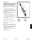
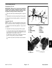
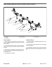
Disassembly (Fig. 41)
IMPORTANT: Make sure to remove and neutralize
chemicals from spray components before disas-
sembly. Wear protective clothing, chemical resist-
ant gloves, and eye protection during repair.
1. Park machine on a level surface, lower spray booms,
stop engine, engage parking brake and remove key
from the ignition switch.
2. Loosen hose clamp and remove supply hose from
tee fitting (item 6) on spray boom.
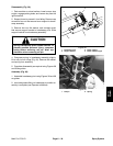
3. Support spray boom to prevent it from falling.
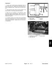
4. Loosen two (2) cap screws (item 9) and lock nuts
(item 8) to allow breakaway springs (item 18) to fully ex-
tend.
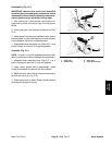
5. Complete disassembly as required using Figure 41
as a guide. If pivot bracket (item 11) is to be removed
from machine, disconnect boom actuator (not shown)
from pivot bracket (see Boom Actuator Removal (Ma-
chines with Serial Numbers Above 260000000) in this
section).
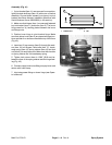
6. Clean all removed components. If pivot bracket was
removed, inspect bushings and pivot pin for damage or
wear.