


Rev. D
Multi Pro 5700--DPage 6 -- 20Spray System
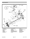
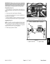
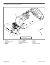
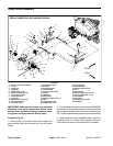
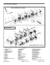
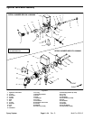
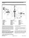
Spray Control Assembly
1. Boom valve motor assembly
2. O--ring
3. Flange nut
4. Flange nut
5. Flange head screw
6. Boom mounting bracket
7. Cross support angle
8. RH boom mount
9. Flange nut
10. Boom hold--in assembly
11. Valve mounting bar
12. LH boom mount
13. Flange head screw
14. R--clamp
15. Support bracket
16. Tee assembly
17. Agitation valve motor
18. O--ring
19. Hosebarb
20. Hose clamp
21. Agitation supply hose (1”)
22. Fork
23. Flange head screw
24. Flange head screw
25. Carriage bolt
26. Mount bracket
27. Boom bypass hose (1”)
28. Fork
29. Hose clamp
30. Boom supply hose (3 used)
31. Boom supply hose (1 1/2”)
32. Hose clamp
33. Hosebarb
34. Pressure gauge tube
35. Hosebarb
Figure 20
3
4
8
1
5
2
6
11
15
12
9
13
10
14
7
4
5
5
5
6
9
9
9
21
16
20
17
10
19
18
24
23
22
3
18
22
26
25
28
27
29
29
30
31
FRONT
RIGHT
32
20
33
34
35
SERIAL NUMBER BELOW 250999999 SHOWN
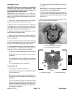
IMPORTANT: Make sure to remove and neutralize
chemicals from spray components before disas-
sembly. Wear protective clothing, chemical resist-
ant gloves, and eye protection during repair.
Removal (Fig. 20)
1. Park machine on a level surface, stop engine, en-
gage parking brake, and remove key from the ignition
switch.
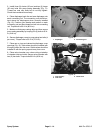
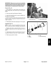
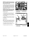
2. On machines with serial number below 310000000,
remove two (2) flange head screws and flange nuts that
secure support bracket (item 15) to mount bracket (item
26). Position bracket away from spray control assembly.
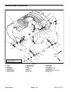
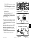
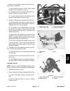
3. Label hoses for proper installation after repairs are
completed (Fig. 21). Loosen hose clamps and discon-
nect hoses from spray control assembly as needed.