


Rev. D
Multi Pro 5700--D Page 6 -- 11 Spray System
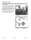
5. Remove lock nuts, flat washers, cap screws, and
coupler spacers that secure rubber coupling to pump
hub.
6. Remove four (4) flange head screws and flange nuts
that secure pump to pump mount bracket.
7. Remove pump from machine.
8. If needed, loosen set screws in pump hub. Pull hub
from pump shaft. Locate and remove key from pump
shaft. Remove set screws from pump hub. Clean
threads of set screws and hub.
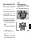
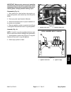
9. If needed, remove pressure dampener, tee fitting
(pressure), and elbow fitting (pressure) from pump out-
let (Fig. 8).
10.If needed, remove suction dampener and tee fitting
(suction) from pump inlet (Fig. 8).
Installation (Fig. 6)
NOTE: Coat all spray system O--rings with vegetable
oil before installation to reduce the chance of damage
during assembly.
1. Apply PTFE tape to threads of removed tee fitting
(pressure), elbow fitting (pressure), and tee fitting (suc-
tion). Position new O--rings and gaskets on suction and
pressure fittings that wereremoved during disassembly.
2. If removed, install tee fitting (suction) and suction
dampener to pump inlet. Orientate tee toward rear of
machine (Fig. 8).
3. If removed, install elbow fitting (pressure), tee fitting
(pressure), and pressure dampener to pump outlet.
Orientate elbow toward rear of machine (Fig. 8).
4. If pump hub was removed, apply antiseize lubricant
to pump shaft. Install k ey in shaft and slide pump hub
onto shaft.
5. Position pump on pumpmounting bracketand install
flange head screws and flange nuts to pump and mount-
ing bracket. Leave fasteners loose.
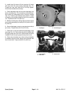
6. Place coupling spacers into rubber coupling. Install
cap screws, flat washers, and locknuts to s ecure rubber
coupling to pump hub. Make sure that cap screw
threads extend through lock nut.
7. If pump hub was removed, apply Loctite #242 (or
equivalent) to threads of pump hub set screws. Install
set screws into pump hub to secure hub to pump shaft.
8. Turn pump shaft by hand and position pump on
mounting bracket to best align the coupling assembly
between the pump shaft and the hydraulic motor shaft.
9. Secure pump to mounting bracket by tightening
flange head screws and flange nuts.
10.Position front and rear guard plates to pump mount
bracket. Install and tighten flange head screw and
flange nut to guard plates. Install flange nuts to secure
guard plates to pump mount bracket.
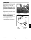
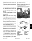
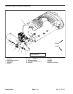
11.Install pressure and suction hoses to correct barbfit-
tings (Fig. 7). Secure hoses with hose clamps.
1. Pressure hose 2. Suction hose
Figure 7
2
1
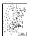
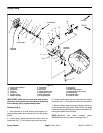
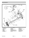
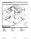
1. Spray pump
2. Pressure hose (1”)
3. Hose clamp
4. Hose barb
5. Nut
6. Gasket
7. Tee fitting (pressure)
8. Elbow fitting (pressure)
9. O--ring
10. Pressure dampener
11. Suction hose (1 1/2”)
12. Hose clamp
13. Nut
14. Seal
15. Tee fitting (suction)
16. Suction dampener
17. Hose barb
Figure 8
2
13
1
3
5
4
6
7
8
9
10
11
14
12
16
15
17
9
6
Spray
System