


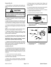

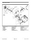

Removal (Fig. 34)
1. Park machine on a level surface, stop engine, en-
gage parking brake, and remove key from the ignition
switch.
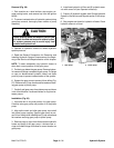
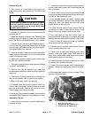
CAUTION
Rotate steering wheel and depress traction ped-
al in both forward and reverse to relieve hydrau-
lic system pressure and to avoid injury from
pressurized hydraulic oil.
2. Operate all hydraulic controls to relieve hydraulic
system pressure.
3. Read the General Precautions for Removing and
Installing Hydraulic System Components at the begin-
ning of the Service and Repairs section of this chapter.
4. To prevent contamination of hydraulic system during
motor removal, thoroughly clean exterior of motor and
fittings.
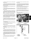
NOTE: To ease reassembly, tag the hydraulic hoses to
show their correct position on the wheel motor.
5. Disconnect hydraulic hoses from fittings on wheel
motor. Put caps or plugs on hydraulic lines, fittings, and
ports to prevent contamination.
6. If right side wheel motor is being removed, unplug
speed sensor connector from machine wiring harness.
IMPORTANT: Before loosening fasteners, support
wheel motor to prevent motor from falling.
7. Support the pump assembly to prevent it from falling.
Remove two (2) cap screws and flat washers that secure
wheel motor to brake and planetary assemblies. Re-
move wheel motor from machine.
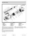
Installation (Fig. 34)
1. If splined brake shaft was removed from brake as-
sembly, make sure that the stepped end of the shaft is
aligned toward the hydraulic wheel motor (Fig. 35). Also,
make sure that splines engage rotating discs in brake
assembly.
2. Position wheel motor to brake assembly.
3. Align splines on motor shaft and splined brake shaft.
Slide motor to brake assembly.
4. Secure motor to brake and planetary assemblies
with cap screws and flat washers. Torque cap screws 60
ft–lb (81 N–m).
5. Remove plugs from hydraulic lines, fittings, and
ports. Lubricate new o–rings and attach hydraulic hoses
to wheel motor.
6. If right side wheel motor was removed, plug speed
sensor connector into machine wiring harness.
7. Check fluid level in hydraulic oil reservoir and adjust
as required (see Operator’s Manual).
8. Operate machine and inspect for leaks.
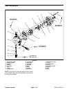
3
1
2
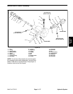
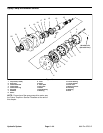
Figure 35
1. Splined brake shaft step 3. Planetary assembly end
2. Hydraulic motor end
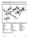
4
1
2
3
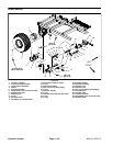
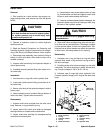
Hydraulic
System
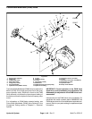
Figure 36
1. Piston (traction) pump 3. Bottom pump fitting
2. Top pump fitting 4. Case drain fitting
Multi Pro 5700–D Page 4 – 39 Hydraulic System