


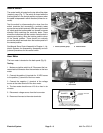
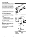
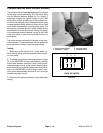
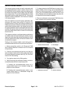


Pressure Rate and Boom Actuator Switches
The pressure rate (increase/decrease) switch is located
on the spray control console (Fig. 25). This switch along
with the Manual Interface Module (or Pro Control, if
equipped) changes the applied current to the PWM
valve which controls hydraulic flow to the hydraulic mo-
tor that drives the spray pump. Pressing the switch to the
increase position allows additional current to the PWM
valve which increases flow to the hydraulic motor. The
spray pump increases speed to allow additional flow
and pressure from the spray pump. Moving the switch
to the decrease position reduces current to the PWM
valve and results in less flow and pressure from the
spray pump.
The boom actuator switches are identical to the pres-
sure rate switch. These switches are used to operate the
boom actuators to raise or lower the spray booms.
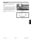
Figure 25
1
2
3
4
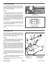
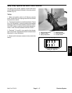
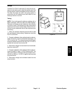
Testing
1. Spray control console 3. RH boom switch
2. Pressure +/– switch 4. LH boom switch
1. Make sure ignition switch is off. Locate switch, re-
move console panel, and unplug wire harness connec-
tor from switch.
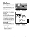
4 5 6
2. The switch terminals are marked as shown in Figure
26. In the INCREASE or boom raise position, continuity
should exist between terminals 2 and 3 and also be-
tween terminals 5 and 6. In the neutral, center position,
there should be no continuity between any switch termi-
nals. In the DECREASE or boom lower position, conti-
1 2 3
nuity should exist between terminals 2 and 1 and also
between terminals 5 and 4.
BACK OF SWITCH
3. Reconnect the harness connector to the switch after
Figure 26
testing.
Electrical System
Page 5 – 16
Multi Pro 5700–D