


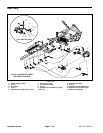
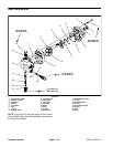

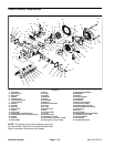
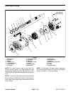

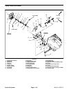
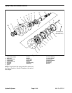

Manual Servo Control Assembly
12
16
11
17
15
14
9
7
4
6
24
22
21
18
5
10
8
13
23
4
3
2
1
28 to 34 in–lb
(3.2 to 3.8 N–m)
17 to 26 in–lb
(1.9 to 2.9 N–m)
44 to 52 ft–lb
(60 to 70 N–m)
Loctite #242
Loctite #222
20
19
Figure 33
1. Plug
9. O–ring
17. Set screw
2. O–ring
10. Wiper seal
18. Set screw
3. Retaining ring
11. O–ring
19. Pin
4. Spring retainer
12. Adaptor
20. Retaining ring
5. Spring
13. Ball
21. Feedback link
6. Spool valve
14. Pin
22. Dowel pin
7. Control housing
15. Neutral switch
23. Bell crank
8. Input shaft
16. O–ring
24. Set screw
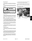
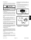
NOTE: For service of the manual servo control assem-
bly (including neutral switch adjustment), see the Eaton
Model 72400 Servo Controlled Piston Pump Repair In-
formation at the end of this chapter.
Hydraulic
System
Multi Pro 5700–D Page 4 – 37 Hydraulic System