


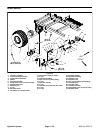


Wheel Motor Service
8
11
9
19
15
20
18
17
12
13
14
10
1
7
4
5
6
4
5
2
3
16
21
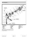
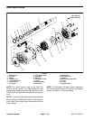
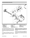
15 to 18 ft–lb
(20 to 24 N–m)
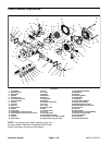
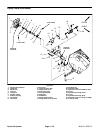
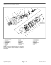
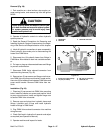
Figure 37
1. Retaining ring
8. Cap screw (6 used)
15. Rotating kit
2. Shaft seal
9. Back plate
16. Cam plate insert
3. Washer
10. Dowel pin
17. Housing
4. Retaining ring
11. Dowel pin (3 used)
18. Speed sensor (RH wheel)
5. Thrust bearing race
12. O–ring
19. O–ring
6. Thrust bearing
13. Needle bearing
20. O–ring
7. Drive shaft
14. Valve plate
21. Needle bearing
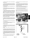
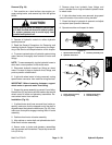
NOTE: The wheel motors used on the Multi Pro
NOTE: For information on speed sensor installation,
5700–D are very similar. The major difference is the
see Traction Speed Sensor in the Service and Repairs
speed sensor installed in the right side wheel motor. Ser-
section of Chapter 5 – Electrical System.
vice of the left and right motors requires the same proce-
dure.
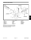
NOTE: For service of the wheel motors, see the Eaton
Model 74318 and 74348 Piston Motors: Fixed Displace-
ment, Valve Plate Design Repair Information at the end
of this chapter.
Hydraulic System Page 4 – 40 Multi Pro 5700–D