


Manual Interface Module
The manual interface module is used in conjunction with
the increase/decrease switch to adjust current flow to
the PWM Valve and to maintain pump rate settings when
the booms are turned off and on again using the master
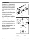
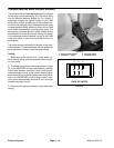
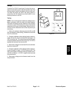
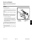
boom (foot) switch. The module is fastened to the head
light shield under the dash panel (Fig. 32). The manual
interface module is disabled if a Pro Control is installed
in the spray system.
Once the operator has set the spray application rate,
whenever the master boom switch is turned off, the
module stores the current (mA) setting available to the
PWM valve solenoid. When the master boom switch is
used to begin spraying again, the module ensures that
the spray application rate is unchanged. Because of the
module, the operator does not have to reset spray rates
when the master boom switch is used to turn the spray
booms back on.
The interface module is a solid state device and there is
no reliable means of bench testing the module. If spray
rates have to be reset after turning the booms off and on
with the master boom switch, the manual interface mod-
ule should be suspect.
Testing of the interface module, circuit wiring and in-
crease/decrease switch can be performed as follows:
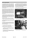
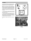
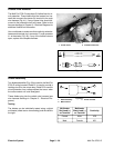
1. Make sure ignition switch is off. Disconnect PWM
Valve solenoid electrical connector from the machine
wiring harness.
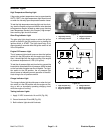
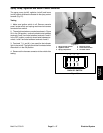
2. Connect one multimeter test lead to one of the har-
ness connector leads and the other meter test lead to
the second harness connector lead (Fig. 33). Set multi-
meter to DC Volts setting.
3. Turn ignition switch to the RUN position.
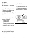
4. While monitoring the multimeter display, use the in-
crease/decrease switch to adjust spray rate:
A. Pressing the increase/decrease switch to in-
crease should result in an increased voltage dis-
played on the multimeter.
B. Pressing the increase/decrease switch to de-
crease should result in a decreased voltage dis-
played on the multimeter.
5. If voltage change to the PWM Valve is correct, the in-
terface module, circuit wiring and increase/decrease
switch are functioning correctly. If voltage change is in-
correct, test increase/decrease switch and then circuit
wiring. Replace manual interface module only after oth-
er components have tested acceptably.
6. Remove multimeter and reconnect PWM Valve elec-
trical connector to the machine harness.
2
1
Figure 32
1. Manual interface module 2. RH headlight
2
1
Figure 33
1. PWM Valve connector 2. Harness connector
Electrical System
Page 5 – 20
Multi Pro 5700–D