


Rev. D
Multi Pro 5700--D
Page 3 -- 12
Kubota Diesel Engine
Engine
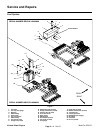
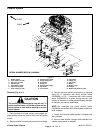
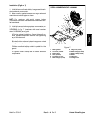
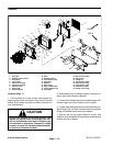
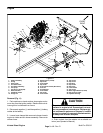
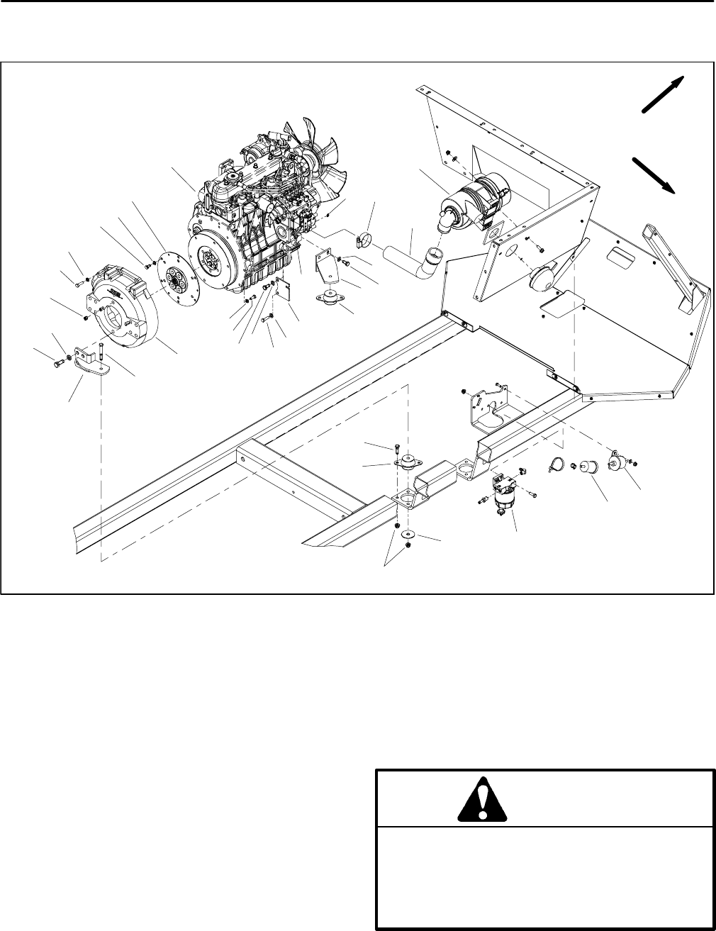
Figure 11
1. Engine assembly
2. E--ring
3. Hose clamp
4. Air cleaner hose
5. Air cleaner assembly
6. Fuel pump
7. Fuel filter (if e quipped)
8. Water/fuel filter
9. Snubbing washer
10. Flange nut
11. Engine mount (4 us e d)
12. Cap screw
13. Lock washer
14. Cap screw
15. Front engine bracket (RH shown)
16. Lock nut
17. Throttle plate
18. Lock washer
19. Cap screw
20. Lock washer
21. Cap screw
22. Cap screw
23. Coupling
24. Cap screw
25. Set screw
26. Lock washer
27. Cap screw
28. Rear engine bracket (2 used)
29. Cap screw (4 used)
30. Flywheel housing
FRONT
RIGHT
9
10
1
7
8
6
3
2
11
4
5
20
21
12
18
19
17
14
13
22
15
16
11
26
27
25
24
28
23
18
18
19
29
18
30
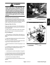
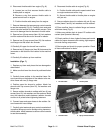
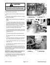
Removal (Fig. 11)
1. Park machine on a level surface, stop engine and re-
move key from t he ignition switch. Raise machine to al-
low engine to be lowered from frame.
2. Disconnect negative (--) and then pos itive (+) battery
cables at the battery.
3. Loosen hose clamps that secure air cleaner hose to
engine air intake and air cleaner assembly. Remove air
cleaner hose.
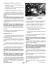
CAUTION
Do not open radiator cap or drain coolant if the
radiator or engine is hot. Pressurized, hot cool-
ant can escape and cause burns. Ethylene--gly-
col antifreeze is poisonous. Dispose of coolant
properly, orstoreit in aproperly labeled contain-
er away from children and pets.
4. Drain coolant from the radiator into a suitable con-
tainer (see Operator’s Manual).