


Multi Pro 5700--D Page 7.1 -- 19 Sonic Boom System (Optional Kit)
Verify Diagnostic Display Output Functions
The Diagnostic Display also has the ability to detect
which output solenoids or relays are energized by the
electronic control unit (ECU). This is a quick way to de-
termine which electrical component is malfunctioning.
NOTE: Anopen output(e.g. an unplugged connector or
a broken wire) cannot be detected with the Diagnostic
Display.
1. Park vehicle on a level surface, stop the engine and
engage the parking brake.
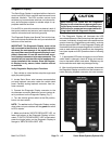
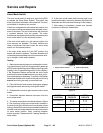
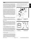
2. Locate Sonic Boom System wire harness and loop-
back connector under the vehicle dash panel. Carefully
unplug loopback connector from harness connector.
3. Connectthe Diagnostic Displayconnector to thehar-
ness connector. Make surecorrect overlay decal is posi-
tioned on the Diagnostic Display (see Special Tools in
this chapter).
4. Turn the ignition switch to the ON position.
NOTE: The red text on the Diagnostic Display overlay
decal refers to input switches and the green text refers
to ECU outputs.
5. Make sure that the “OUTPUTS DISPLAYED” L ED,
on lower right column ofthe Diagnostic Display, is illumi-
nated. If “INPUTS DISPLAYED” LED is illuminated,
press the toggle button on the Diagnostic Display to
change the LED to “OUTPUTS DISPLAYED”.
NOTE: It may be necessary to toggle between “IN-
PUTS DISPLAYED” and “OUTPUTSDISPLAYED” sev-
eral times to perform the following step. To change from
inputs to outputs, press toggle button once. This may be
done as often as required. Do not press and hold
toggle button.
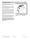
6. Attempt to operate the desired function of the ma-
chine. The appropriate output LED’s should illuminate
on the Diagnostic Display to indicate that the ECU is
turning on that function. The outputs can be checked
with the vehicle ignition switchin the ON position and the
engine not running.
A. Ifthe correct output LED’s donot illuminate, verify
that the required input switches are in the necessary
positions to allow that function to occur.
B. If the output LED’s are on as specified, but the
booms do not function properly, suspect a failed
electrical component, an open in the tested circuit or
a non-electrical problem (e.g. binding of the boom
hinge). Repair as necessary.
C. If each input switch is in the correct position and
functioning correctly, but the output LED’s are not
correctly illuminated, thisindicates an ECU problem.
If this occurs, contact your Toro Distributor for assis-
tance.
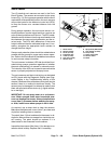
7. After output functions testing is complete, discon-
nect the Diagnostic Display connector from the harness
connector and plug loopback connector into wire har-
ness.
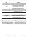
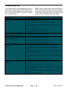
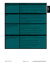
Diagnostic Display
Outputs
Diagnostic Display
LED Operation
L BOOM -- RAISE Left boom is rising: LED ON
Left boom is stationary: LED OFF
R BOOM -- RAISE Right boom is rising: LED ON
Right boom is stationary: LED OFF
POWER ON/ERROR Power to ECU: LED ON
No power to ECU: LED OFF
System error: LED flashing slowly
L BOOM MOTOR ECU output exists to energize left power switch relay: LED ON
No ECU output to left power switch relay: LED OFF
R BOOM MOTOR ECU output exists to energize right power switch relay: LED ON
No ECU output to right power switch relay: LED OFF
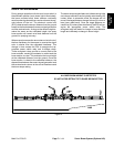
Sonic Boom
System