


Pulse Width Modulated (PWM) Valve Flow Test
1. Make sure hydraulic oil is at normal operating tem-
perature by operating the machine for approximately 10
minutes. Make sure the hydraulic tank is full.
2. Park machine on a level surface, stop engine, en-
gage parking brake, and remove key from the ignition
switch. After turning engine off, operate all hydraulic
controls to relieve hydraulic system pressure.
3. Perform the Gear Pump Flow Test. Make sure that
spray motor circuit hydraulic flow has been tested and
recorded.
CAUTION
of this section.
Prevent personal injury and/or damage to equip-
ment. Read all WARNINGS, CAUTIONS, and Pre-
cautions for Hydraulic Testing at the beginning
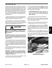
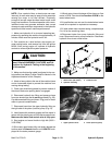
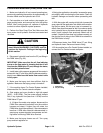
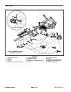
4. Disconnect hydraulic hose from the CF port fitting in
the PWM Valve (Fig. 22).
IMPORTANT: Make sure that the oil flow indicator
arrow on the flow meter is showing that the oil will
flow from the PWM Valve CF port, through the tester,
and into the hydraulic hose.
5. Install tester with pressure gauges and flow meter in
series with the CF port fitting and the disconnected hy-
draulic hose. Make sure the tester flow control valve
is fully open.
6. Make sure that spray tank has sufficient fluid for
agitation. Make sure that spray pump is turned off.
7. If the machine has a Pro Control System installed,
disconnect the Pro Control console computer.
8. Start engine and move throttle to high idle speed
(3050 – 3150 RPM). The flow meter should indicate
little, if any, hydraulic flow (less than 1 GPM) from the
PWM Valve CF port.
A. If higher flow exists, stop engine, disconnect the
PWM Valve solenoid connection from the machine
harness and retest. If higher flow still exists, the
PWM Valve should be replaced. If flow decreases to
less than 1 GPM after solenoid is disconnected, in-
spect spray system electrical components and wir-
ing before continuing PWM Valve flow test.
9. Make sure that spray booms are off. Turn spray
pump and tank agitation on.
10.Using the application rate switch, increase the spray
rate slightly while monitoring the flow tester. Check for
hydraulic leakage and correct before proceeding with
test.
11. With the engine still running at high idle, increase the
spray rate with the application rate switch while monitor-
ing the flow tester. As the spray rate is increased, hy-
draulic flow should increase as well. At maximum spray
rate, hydraulic flow on the tester should approach spray
motor circuit hydraulic flow previously tested and re-
corded. If hydraulic flow does not increase correctly, ei-
ther the the circuit wiring to the PWM Valve solenoid or
the PWM Valve is faulty.
12.Disconnect tester from PWM Valve CF port fitting
and hydraulic hose. Reconnect hose to fitting.
13.If the machine has a Pro Control System installed, re-
connect the Pro Control console computer.
3
1
2
Figure 22
1. PWM Valve 3. PWM Valve solenoid
2. CF port fitting
Hydraulic System Page 4 – 24 Multi Pro 5700–D