


Battery Service
The battery is the heart of the electrical system. With
regular and proper service, battery life can be extended.
Additionally, battery and electrical component failure
can be prevented.
CAUTION
When working with batteries, use extreme cau-
eyes. Always wear safety goggles and a face
shield when working with batteries.
tion to avoid splashing or spilling electrolyte.
Electrolyte can destroy clothing and burn skin or
Electrolyte Specific Gravity
Fully charged: 1.265 corrected to 80
o
F (26.7
o
C)
Discharged: less than 1.240
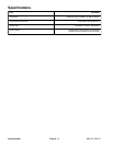
Battery Specifications
BCI Group Size 34
690 CCA at 0
o
F (–18
o
C)
Reserve Capacity of 100 minutes at 80
o
F (27
o
C)
Dimensions (including terminal posts)
Length 10.17 inches (25.8 cm)
Width 6.65 inches (16.9 cm)
Height 7.98 inches (20.3 cm)
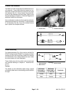
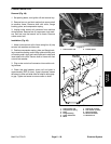
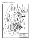
Battery Removal (Fig. 49)
IMPORTANT: Be careful not to damage battery ter-
minal posts or cable connectors when removing the
battery cables.
1. Make sure ignition and all accessories are OFF.
2. Using two wrenches, loosen cap screw and nut on
ground (–) cable connector first and then remove
ground (–) cable from battery. This should prevent short
circuiting the battery, other components or the opera-
tors’ hands.
3. Loosen cap screw and nut on positive (+) cable con-
nector using two wrenches. Remove positive (+) cable
from battery.
4. Loosen cap screw and flange nut that secure battery
retainer to the battery compartment.
5. Make sure battery vent caps are on tightly.
6. Remove battery from the battery compartment to a
service area to allow better access for service.
Battery Installation (Fig. 49)
IMPORTANT: To prevent possible electrical prob-
lems, install only a fully charged battery.
1. Make sure ignition and all accessories are OFF.
Multi Pro 5700–D
2. Make sure battery compartment is clean and re-
painted if necessary. Make sure all battery cables, con-
nections and battery retainer are in good condition.
3. Place battery in its compartment with the battery
posts toward the rear of the vehicle. Make sure battery
is level and flat.
4. Secure battery retainer. Do not overtighten to pre-
vent cracking or distorting the battery case.
5. Connect positive (+) cable connector onto positive
battery post. Tighten cap screw and nut using two
wrenches.
6. Connect a digital multimeter (set to amps) between
the negative battery post and the ground (–) cable con-
nector. The reading should be less than 0.1 amp. If the
reading is 0.1 amp or more, the unit’s electrical system
should be tested and repaired.
7. Connect ground (–) cable connector to the negative
battery post. Tighten cap screw and lock nut using two
wrenches.
8. Coat battery posts and cable connectors with Battery
Terminal Protector (Toro Part No. 107–0392) or petro-
leum jelly to prevent corrosion.
1
2
3
Figure 49
1. Battery 3. Negative battery cable
2. Positive battery cable
Electrical
System
Page 5 – 31
Electrical System