


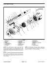

Multi Pro 5700--D Hydraulic SystemPage 4 -- 35
3. Operate all hydraulic controls to relieve hydraulic
system pressure.
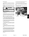
4. Remove traction cableball joint from control plate on
piston pumpby removing lock nut (Fig.32). Remove cap
screw from control plate. Locate and retrieve three (3)
flat washers (Fig. 33).
5. Disconnect two (2) wires from neutral switch on pis-
ton pump (Fig. 32).
6. Remove flange head screw and flange nut that se-
cures R --clamp and right side brake cable to pump as-
sembly (Fig. 32).
7. Read the General Precautions for Removing and
Installing Hydraulic System Components at the begin-
ning of the Service and Repairs section of this chapter.
NOTE: To ease reassembly, tag hydraulic hoses to
show their correct position on the pump assembly.
8. Put a drain pan below the pump assembly. Remove
hydraulic hoses and fittings connected to piston and
gear pumps. Put plugs or capson disconnectedhydrau-
lic hoses to prevent contamination of the system. Put
plugs in open ports of pumps.
9. Support the pump assembly to prevent itfrom falling.
Remove two (2) cap screws, lock washers and flat
washers that retain pump assembly to engine bell hous-
ing.
10.Carefully pullpump assemblyfrom engineand lower
it out of the machine.
11.If needed, separate gear pump from piston pump
(see Gear Pump Removal in this section).
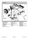
Installation (Fig. 31)
1. If gear pump was removed from piston pump, install
gear pump to piston pump (see Gear Pump Installation
in this section).
2. Apply antiseize lubricant to piston pump shaft
splines.
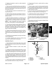
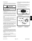
3. Carefully raise pump assembly and position it to the
engine. Make sure that both bushings on control plate
are between centering arms on rear of engine (Fig. 32).
4. Align spline teeth and slide piston pump input shaft
into engine coupling spline. Support pump to prevent it
from falling while installing two (2) cap screws, lock
washers and flat washers to secure pump to engine bell
housing.
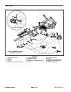
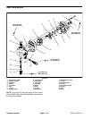
5. Secure traction cableto control plate with capscrew,
three (3) washers and lock nut (Fig. 32 and 33).
6. Connect two (2) wires to neutral switch on piston
pump (Fig. 32).
7. Remove plugs or caps from disconnected hydraulic
hoses and ports of the pump assembly. Lubricate new
O--rings and install fittings and hoses to correct location
on gear and piston pumps.
8. Secure R--c lamp and right side brake cable to pump
assembly with flange head screw and flange nut.
9. Install new hydraulic oil filter and fill hydraulic reser-
voir with correct oil (see Operator’s Manual).
10.Properly fill hydraulic system (see Charge Hydraulic
System in the Service and Repairs section of this chap-
ter).
11.Stop engine and check for hydraulic oil leaks. Check
hydraulic reservoir oil level.
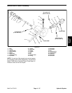
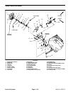
1. Traction cable lock nut
2. Neutral switch
3. R--clamp/brake cable
4. Centering arm
Figure 32
2
1
3
4
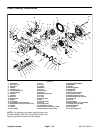
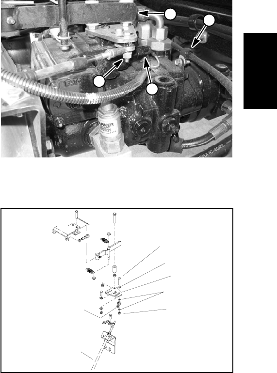
1. Cap screw
2. Flat washer
3. Neutral plate
4. Flat washer
5. Lock nut
6. Ball joint
7. Traction cable
Figure 33
3
5
4
2
1
6
7
Hydraulic
System