


Rev. D
Multi Pro 5700--DHydraulic System Page 4 -- 46
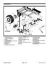
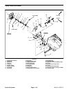
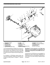
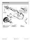
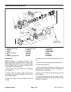
Pulse Width Modulated (PWM) Valve
1. Spray pump assembly
2. Flange nut
3. Flange head screw
4. Rear guard plate
5. Flange nut (3 used)
6. Front guard plate
7. Hydraulic hose (PWM to motor)
8. O--ring
9. Hydraulic fitting
10. O--ring
11. Cap screw (2 used)
12. PWM Valve
13. Hydraulic hose (from gear pump)
14. Hydraulic tee fitting
15. Hydraulic hose (to oil cooler)
16. O--ring
17. Hydraulic hose (motor to PWM tee)
18. Flat washer (2 used)
19. Hydraulic motor
20. Pump mount bracket
Figure 44
FRONT
RIGHT
1
3
5
8
10
9
12
13
14
15
17
7
11
6
4
2
16
7
9
8
10
17
5
18
19
20
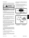
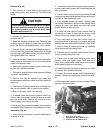
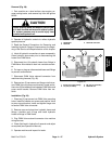
The Pulse WidthModulated (PWM)Valve is used on the
Multi Pro 5700--D to control gear pump flow to the spray
pump hydraulic motor. Electrical current to the PWM
Valve solenoid coil affects the internal spool setting of
the Valve and thus the hydraulic flow to the spray pump
motor.
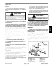
For information on PWM Valve solenoid testing, see
Pulse Width Modulated (PWM) Valve Solenoid in the
Component Testing section of Chapter 5 -- Electrical
System.
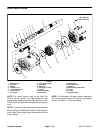
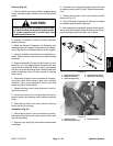
IMPORTANT: C orrect operation of the PWM Valve
depends on precise assembly and adjustment. No
disassembly or adjustment of the PWM Valve is rec-
ommended.
Internal parts for the PWM valve are not available. On
machines with serial numbers above 260000300, the
PWM valve solenoid c oil is available asa separatecom-
ponent. Refer to your parts catalog for replacement part
information.