


Multi Pro 5700--D Page 7.1 -- 17 Sonic Boom System (Optional Kit)
Diagnostic Display
The Sonic Boom System is equipped with an electronic
control unit (ECU) which controls machine sonic boom
electrical functions. The ECU monitors various input
switches (e.g. boom actuatorswitches, sonic boom sen-
sors) and energizes outputs to actuate relays for ap-
propriate machine functions.
For the ECU to control the machine as desired, each of
the inputs (switches and sensors) and outputs (relays)
must be connected and functioning properly.
The Diagnostic D isplay (see Special Tools in this chap-
ter) is a toolto help the technicianverify correct electrical
functions of the machine.
IMPORTANT: The Diagnostic Display must not be
left connected to the machine. It is not designed to
withstand the environment of the machine’s every
day use. When use of the Diagnostic Display is com -
pleted, disconnect it from the machine and recon-
nect loopback connectorto harness connector. The
machine will not operate without the loopback con-
nector installed on the harness. Store the Diagnos-
tic Display in a dry, secure, indoor location and not
on machine.
Verify Diagnostic Display Input Functions
1. Park vehicle on a level surface, stop the engine and
apply the parking brake.
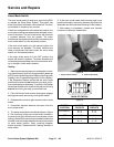
2. Locate Sonic Boom wire harness communication
port and loopback connector under the v ehicle dash
panel. C arefully unplug loopback connector from har-
ness connector.
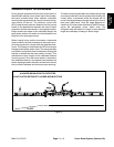
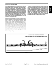
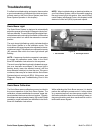
3. Connect the Diagnostic Display connector to the
wire harness connector. Make sure correct overlay de-
cal is positioned on the Diagnostic Display (Fig. 7).
4. Turn the v ehicle ignition switch to the ON position,
but do not start vehicle.
NOTE: The red text on the Diagnostic Display overlay
decal refers to input switches and the green text refers
to ECU outputs.
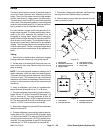
5. Make sure that the “INPUTS DISPLAYED” LED, on
lower right column of the Diagnostic Display, is illumi-
nated. If “OUTPUTS DISPLAYED” LED is illuminated,
press the toggle button on the Diagnostic Display to
change to “INPUTS DISPLAYED” LED.
CAUTION
When testing ECU inputs with the Diagnostic
Display, boom actuators may be energized caus-
ing the spray booms to move. Be cautious of po-
tential sprayer component movement while veri-
fying inputs with the Diagnostic Display.
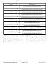
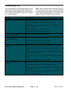
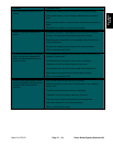
6. The Diagnostic Display will illuminate the LED
associatedwith each ofthe inputs whenthat input switch
is closed. Individually, change each of the switches from
open to closed (e.g. togglesonic mode switch), and note
that the appropriate LED on the Diagnostic D isplay will
illuminate when the corresponding switch is closed. Re-
peat on each switch that is possible to be changed by
hand (see Inputs and LED Operation chart on following
page).
7. If appropriate LED does not toggle on and off when
switch state is changed, check all wiring and connec-
tions to that switch and/or test switch. Replace any de-
fective switches and repair any damaged wiring.
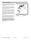
8. After input functions testing is complete, disconnect
the Diagnostic Display connector from the harness con-
nector and plug loopback connector into wire harness.
Figure 7
Sonic Boom
System