


Multi Pro 5700–D Hydraulic SystemPage 4 – 45
Relief Valve
Removal
1. Park machine on a level surface, stop engine, en-
gage parking brake, and remove key from the ignition
switch.
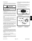
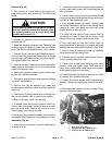
CAUTION
Rotate steering wheel and depress traction ped-
al in both forward and reverse to relieve hydrau-
lic system pressure and to avoid injury from
pressurized hydraulic oil.
2. Operate all hydraulic controls to relieve hydraulic
system pressure.
3. Read the General Precautions for Removing and
Installing Hydraulic System Components at the begin-
ning of the Service and Repairs section of this chapter.
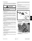
4. Disconnect hose assembly from hydraulic fitting at
bottom of relief valve body. Allow hose to drain into a
suitable container.
5. Unscrew relief valve body from hydraulic adapter in
side of piston pump.
6. If needed, remove hydraulic fitting from bottom of re-
lief valve body.
Installation
1. Lubricate new o–rings with clean hydraulic fluid.
2. If removed, install hydraulic fitting into bottom of re-
lief valve body.
3. Secure valve body to the hydraulic adapter in side of
piston pump.
4. Install hydraulic hose to hydraulic fitting at bottom of
relief valve body. Tighten hose connections.
Disassembly
1. Unscrew relief valve cartridge from the relief valve
body. Remove o–ring and back–up ring.
2. Inspect ports of the relief valve body for damaged
sealing surfaces or threads and contamination.
3. Inspect relief valve cartridge for damaged sealing
surfaces and contamination.
A. Contamination may cause valves to stick or hang
up. Contamination can become lodged in small valve
orifices or seal areas causing malfunction.
B. If sealing surfaces appear pitted or damaged, the
hydraulic system may be over heating or there may
be water in the hydraulic system.
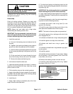
CAUTION
Use eye protection such as goggles when using
compressed air.
4. Clean relief valve cartridge using clean mineral spir-
its to flush out any contamination. Submerge cartridge
in clean mineral spirits to flush out contamination. Par-
ticles as fine as talcum powder can affect the operation
of relief valve. Use compressed air for cleaning.
Reassembly
1. Lubricate new o–ring and back–up ring with clean
hydraulic fluid. Install o–ring and back–up ring to the re-
lief valve cartridge.
2. Carefully thread relief valve cartridge into the relief
valve body. The valve should go in easily without bind-
ing. Torque cartridge to 190 in–lb (21.4 N–m).
3. Lubricate new O–rings with clean hydraulic fluid.
Connect hydraulic fittings and O–rings to the relief valve
body.
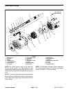
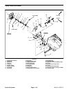
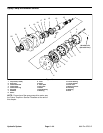
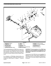
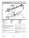
1. Pump assembly
2. O–ring
3. Hydraulic adapter
4. O–ring
5. Relief valve body
6. Relief cartridge
7. Seal kit
8. Hydraulic fitting
9. O–ring
10. Hydraulic hose
Figure 41
2
7
8
9
5
6
3
1
10
4
190 in–lb
(21.5 N–m)
Hydraulic
System