


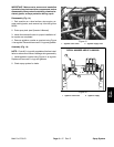
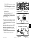

3. Install three (3) shorter (30 mm) and two (2) longer
(55 mm) bolts into pump casing assembly (Fig. 11).
Thread hex nuts onto bolts but do not fully tighten.
Check that crankshaft turns freely.
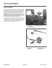
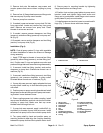
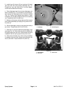
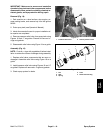
4. Place diaphragm back disc and new diaphragm onto
each connecting rod. The connecting rods should ex
-
tend above the diaphragms when correctly installed
(Fig. 12). Position nylon washer and washer on each
connecting rod and then thread hex bolt into connecting
rod. Torque bolt to 60 ft–lb (80 N–m).
5. Make sure that pump casings align and then secure
pump casing assembly by torquing five (5) bolts to 32 ft–
lb (44 N–m).
6. Secure diaphragm covers to pump using hex bolts (4
per cover). Torque bolts to 55 ft–lb (75 N–m).
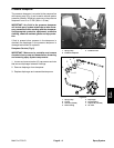
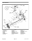
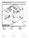
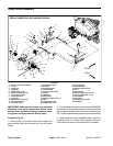
7. Place new o–rings and valves into diaphragm cover
openings (Fig. 13). Inlet valves should be installed with
the spring down into the cover. Outlet valves should be
installed in with the spring up and away from cover.
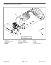
8. Place valve chamber over valves noting orientation
of chamber inlet and outlet. Secure valve chamber with
two (2) hex bolts. Torque bolts 60 ft–lb (80 N–m).
2
1
Figure 12
1. Diaphragm 2. Connecting rod
2
2
1
3
Figure 13
1. Inlet (suction) 3. Outlet valve
2. Inlet valve
Spray System
Page 6 – 14
Multi Pro 5700–D