


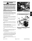

CAUTION
Exhaust system components may be hot. To
avoid possible burns, allow the exhaust system
to cool before working on or near the muffler.
5. Remove exhaust system from engine (see Exhaust
System Removal in this section).
6. Remove upper and lower radiator hoses from en-
gine.
7. Disconnect engine electrical connections. Position
wires away from engine.
NOTE: Label all electrical leads for reassembly pur-
poses.
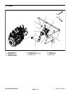
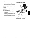
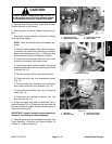
A. Remove positive battery cable, cable to accesso-
ry solenoid and fusible link connector from electric
starter motor solenoid stud (Fig. 11). Remove cable
tie that secures fusible link connector to starter.
B. Disconnect wire harness white wire and violet/
white wire connectors from starter motor.
C. Remove cap screw and lock washer that secure
negative battery cable and wire harness ground wire
to engine (Fig. 11).
D. Remove orange wire from glow plug terminal.
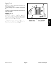
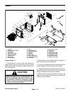
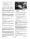
E. Disconnect blue wire from temperature sender
(Fig. 12).
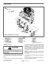
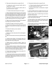
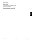
F. Remove cable from alternator stud. Disconnect
wire harness connector from alternator (Fig. 13).
G. Disconnect brown/white wire from oil pressure
switch (Fig. 13).
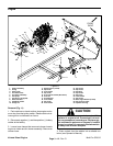
H. Disconnect wire harness connector from fuel
stop solenoid (Fig. 14).
8. Clamp fuel supply hose after the water/fuel filter to
prevent leakage (Fig. 14). Disconnect fuel hose from the
fuel injector pump on engine. Position disconnected fuel
hose away from engine.
IMPORTANT: Support hydraulic pump assembly to
prevent it from falling and being damaged.
9. Remove hydraulic pump assembly from engine (see
Pump Assembly in Service and Repairs section of
Chapter 4 – Hydraulic System).
4
2
3
1
Figure 11
1. Starter motor stud 3. Harness ground wire
2. Negative battery cable 4. Motor mount
1
Figure 12
1. Temperature sender
3
4
2
1
Figure 13
1. Alternator 3. Harness connector
2. Alternator stud 4. Oil pressure switch
Kubota Diesel
Engine
Multi Pro 5700–D Page 3 – 13 Kubota Diesel Engine