


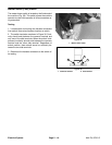

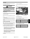
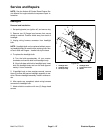

Glow Relay
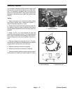
The glow relay is attached to the electric panel under the
operator seat (Fig. 36). When energized, the glow relay
allows electrical current to the engine glow plugs.
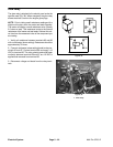
NOTE: Prior to taking small resistance readings with a
digital multi meter, short the meter test leads together.
The meter will display a small resistance value (usually
0.5 ohms or less). This resistance is due to the internal
resistance of the meter and test leads. Subtract this val-
ue from from the measured value of the component you
are testing.
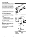
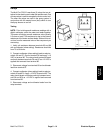
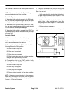
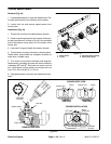
85 86
87
30
86 87
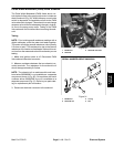
1. Verify coil resistance between terminals 85 and 86
with a multimeter (ohms setting). Resistance should be
approximately 72 ohms.
85 30
2. Connect multimeter (ohms setting) leads to relay ter-
minals 30 and 87. Ground terminal 86 and apply +12
VDC to terminal 85. The relay should make and break
continuity between terminals 30 and 87 as +12 VDC is
Figure 35
applied and removed from terminal 85.
3. Disconnect voltage and leads from the relay termi-
nals.
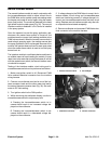
1
Figure 36
1. Glow relay
Electrical System
Page 5 – 22
Multi Pro 5700–D