


Rev. D
Multi Pro 5700--D
Page 5 -- 19
Electrical System
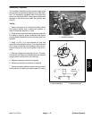
Pulse Width Modulated (PWM) Valve Solenoid
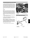
The Pulse Width Modulated (PWM) Valve which con-
trols hydraulic flow to the spray pump motor includes an
electric solenoid (Fig. 30). When the spray console rate
switch is depressed, the available current to the PWM
valves olenoid is changed.This solenoid currentchange
causes a valve shift and subsequent change in hydrau-
lic flow to the spray pump motor. Testing of the PWM
Valve solenoid can be done without removing the sole-
noid.
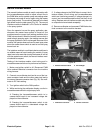
Testing
NOTE: Prior to taking small resistance readings with a
digital multimeter, short the meter test leads together.
The meter will display a small resistance value (usually
0.5 ohms or less). This resistance is due to the internal
resistance of the meter and test leads. Subtract this val-
ue from from the measured value of thesolenoid y ou are
testing.
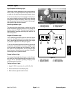
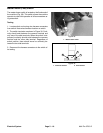
1. Make sure ignition switch is off. Disconnect PWM
Valve solenoid electrical connector.
2. Measure resistance between the two solenoid con-
nector terminals. The resistance for the solenoid coil
should be approximately 9.6 ohms.
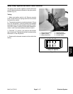
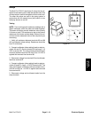
NOTE: The solenoid coil on machines with serial num-
bers below 260000300 is not available as a separate
component (shown in Fig. 30). On machines with serial
numbers above 260000300, the coil is available as a
separate component (Fig. 31). Refer to your parts cata-
log for replacement part information.
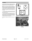
3. Reconnect electrical connector to the solenoid.
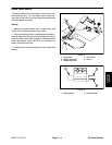
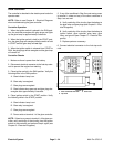
1. PWM valve
2. Solenoid
3. Solenoid connector
Figure 30
3
2
1
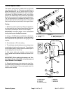
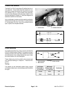
1. PWM valve
2. Solenoid coil
3. O--ring
4. Nut
Figure 31
3
2
4
1
SERIAL NUMBER ABOVE 260000300
Electrical
System