


Multi Pro 5700--DPage 7.1 -- 22Sonic Boom System (Optional Kit)
Service and Repairs
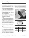
Sonic Mode Switch
The sonic mode switch is used as an input for the ECU
to activate the Sonic Boom System. This switch has
three (3) positions: automatic,manual and off.The sonic
mode switch is located on the console.
If the sonic mode switch is in the automatic position, the
sonic sensors w ill beactivated to allow automaticmove-
ment of the boom. The tips of the booms will remain at
a constant distance from the ground. The boom
switches canbe used to raise/lowerthe booms when the
sonic mode switch is in the automatic position.
If the sonic mode switch is in the manual position, the
sonic sensors are disabled. The boom switches are
used to raise/lower the booms when the sonic mode
switch is in the manual position.
If the sonic mode switch is in the OFF position, the
booms will remain in position. The boom actuators will
not be energized regardless of sonic boom sensor activ-
ity or change in boom switch position.
Testing
1. Before disconnecting the sonic mode switch for test-
ing, the switch and its circuit wiring should be tested as
a ECU input withthe D iagnostic Display (seeDiagnostic
Display in the Troubleshooting section of this chapter).
If the Diagnostic Display verifies that the sonic mode
switch and circuit wiring are functioning correctly, no fur-
ther switch testing is necessary. If, however, the Display
determines that the sonic mode switchand circuit wiring
are not functioning correctly, proceed with test.
2. Park vehicle on a level surface, stop engine, engage
parking brake and remove key from ignition switch.
3. Disassemble console to gain access to sonic mode
switch.
4. Disconnect harness electrical connector from the
sonic mode switch.
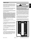
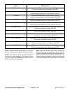
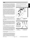
5. The s witch terminals are marked as shown in Figure
9. The circuit logic of the sonic mode switch is shown in
the chart to the right. With the use of a multimeter (ohms
setting), theswitch functions may be testedto determine
whether continuity exists between the various terminals
for each switch position. Verify continuity between
switch terminals. Replace switch if testing identifies a
faulty switch.
6. If the sonic mode switch tests correctly and circuit
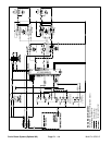
problem still exists, check wire harness (see Electrical
Schematic and Wire Harness Drawings in this chapter).
7. After testing is completed, connect wire harness
connector to the sonic mode switch.
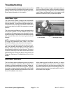
1. Spray control console 2. Sonic mode switch
Figure 8
1
2
Figure 9
BACK OF SWITCH
SWITCH
POSITION
CLOSED
CIRCUITS
OPEN
CIRCUITS
AUTOMATIC 2+3
5+6
2+1
5+4
OFF NONE ALL
MANUAL 2+1
5+4
2+3
5+6