


Rev. C
Multi Pro 5700--D ChassisPage 7 -- 15
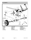
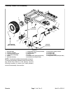
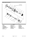
Removal (Fig. 13)
1. Park machine on a level surface, stop engine, en-
gage parking brake, and remove key from the ignition
switch.
2. Drain oil from planetary wheel drive/brake assembly
(see Operator’s Manual).
CAUTION
When changing attachments, tires, or perform-
ing other service, use correct blocks, hoists,
and jacks. Make sure machine is parked on a
solid, level surface such as a concrete floor.
Prior to raising machine, remove any attach-
ments that may interfere with the safe and
proper raising of themachine. Always chock or
block wheels. Use jack stands or solid wood
blocks to support theraised machine. If the ma-
chine is not properly supported by blocks or
jack stands, the machine may move or fall,
which may result in personal injury.
3. Chock front wheels and jack up rear of machine (see
Jacking Instructions in Operator’s Manual). Support
machine with jack stands or solid wood blocks.
4. Remove rear wheel assembly.
5. Support wheel motor and brake assembly to prevent
them from shifting during planetary removal.
6. Remove two (2) cap screws and flat washers that se-
cure wheel motor to planetary assembly.
7. Remove four (4) flange head screws that secure
brake assembly to planetary assembly (see Brake As-
sembly).
8. Supportplanetary assembly to preventit from falling.
Loosen and remove eight (8) flange head screws that
secure planetary assembly to frame. Remove planetary
assembly from machine.
Installation (Fig. 13)
1. Make sure that gasket surfaces of planetary and
brake assembly arec lean. Position new gasket to brake
assembly.
2. Position planetary assembly to machine making
sure to engage splined brake shaft with planetary drive
shaft. Installeight (8) flangehead screws to secure plan-
etary assembly to frame. Torque screws 60 ft--lb (81
N--m).
3. Make sure that gasket is properly positioned and
then secure brake assemblyto planetary (see Brake As-
sembly).
4. Secure wheel motor to planetary with two (2) cap
screws and flat washers. Torque screws 60 ft--lb (81
N--m).
WARNING
Failure to maintain proper wheel lug nut
torque could result in failure or loss of wheel
and may result in personal injury.
5. Install wheel assembly with valve stem facing out.
Torque lug nuts from 70 to 90 ft--lb (95 to 122 N--m).
6. Lower machine from jack stands.
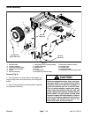
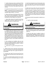
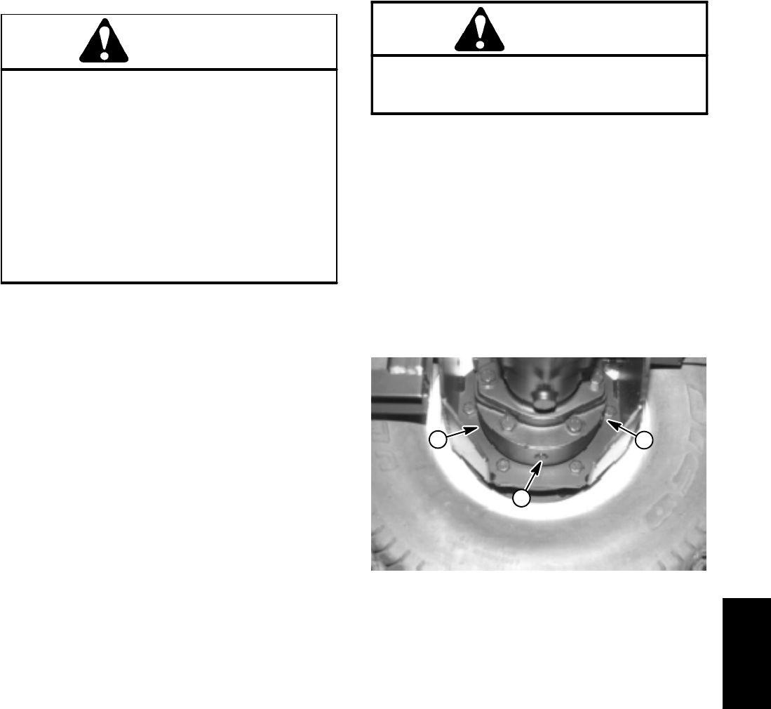
7. Make sure drain plug is installed in bottom of brake
assembly (Fig. 14). Fill planetary wheel drive/brake as-
sembly to proper level with SAE 85W--140 gear lube
(see Operator’s Manual). Capacity is approximately 16
oz. (.47 l) per wheel.
8. Check and adjust brake cables for proper brake op-
eration (see Operator’s Manual).
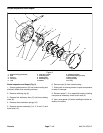
1. Brake housing
2. Check plug
3. Drain plug
Figure 14
3
2
1
Chassis