


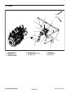
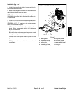


6. Disconnect throttle cable from engine (Fig. 8).
A. Loosen jam nut that secures throttle cable to
throttle plate on engine.
B. Remove e–ring that secures throttle cable to
speed control lever on engine.
C. Position throttle cable away from the engine.
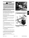
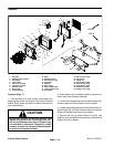
7. Remove fasteners that secure spray control console
to seat box assembly (Fig. 9). Carefully pivot seats and
control console forward to allow radiator access. Take
care not to damage the wire harness or throttle cable.
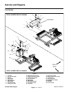
8. Remove four (4) cap screws (item 19), lock washers
and flat washers that secure fan shroud to radiator.
9. Remove two (2) cap screws (item 22), flat washers
and flange nuts that attach fan shrouds.
10.Carefully lift upper fan shroud from machine.
11. Remove two (2) flange nuts (item 26) that secure the
isomounts on the bottom of the radiator to the machine
frame.
12.Carefully lift radiator up from machine.
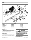
Installation (Figs. 7)
1. Replace any foam seal pieces that are damaged or
deteriorated.
2. Make sure that lower fan shroud is positioned below
fan.
3. Carefully lower radiator to the machine frame. Se-
cure isomounts on the bottom of the radiator to the ma-
chine frame with two (2) flange nuts.
4. Position upper fan shroud to radiator. Attach fan
shrouds with cap screws (item 22), flat washers and
flange nuts.
5. Secure radiator shrouds to radiator with four (4) cap
screws (item 19), lock washers and flat washers. Make
sure that clearance exists between radiator shrouds
and fan at all points before tightening fasteners.
6. Connect lower and upper hoses to the radiator. Se-
cure hoses with hose clamps.
7. Carefully pivot seats and spray control console back
in position taking care not to damage wiring harness or
throttle cable. Install fasteners to secure control console
to seat box assembly.
8. Reconnect throttle cable to engine (Fig. 8).
A. Position throttle cable end to speed control lever
on engine and secure with e–ring.
B. Secure throttle cable to throttle plate on engine
with jam nut.
9. Secure radiator shroud to radiator with six (6) cap
screws (items 5 and 6), lock washers and flat washers.
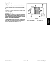
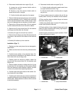
10.Place overflow hose to radiator flange and secure
with hose clamp (Fig. 9).
11. Make sure radiator drain is closed. Fill radiator with
coolant (see Operator’s Manual).
12.Check position of wires, hydraulic hoses and control
cables for proper clearance with rotating, high tempera-
ture and moving components.
13.Start engine and check for proper operation. Check
all hose connections for leaks.
1
2
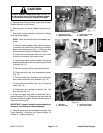
Figure 8
1. Throttle cable 2. Throttle plate
1
2
2
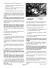
Figure 9
1. Overflow hose 2. Spray console fastener
Kubota Diesel
Engine
Multi Pro 5700–D Page 3 – 11 Kubota Diesel Engine