


Rev. D
Multi Pro 5700--D Page 3 -- 9 Kubota Diesel Engine
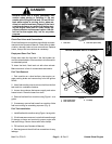
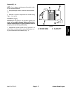
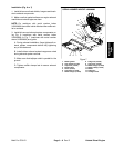
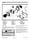
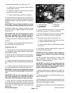
Installation (Fig. 6 or 7)
1. Install all removed heat shields, hangers and brack-
ets to exhaust components.
2. Make sure that gasket surfaces on engine exhaust
manifold and exhaust pipe are clean.
NOTE: On machines with serial number below
310000000, the muffler inlet is offset andthe muffler out-
let is centered.
3. Install all removed exhaust system components us-
ing Fig. 6 (machines with serial number below
310000000) or Fig. 7 (machines with serial number
above 310000000) as a guide.
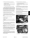
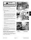
A. During exhaust installation, finger tighten all ex-
haust system components before fully tightening
any of the fasteners.
B. Install rubber exhaust system hangers as noted
during exhaust system removal.
C. Make sure that tailpipe outlet is parallel to the
ground.
D. Tighten muffler clamps las t to secure exhaust
components.
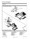
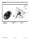
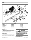
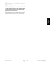
Figure 7
1. Muffler gasket
2. Lock washer ( 4 u sed)
3. Cap screw ( 4 used)
4. Exhaust pipe
5. Screw ( 2 used)
6. Flat washer (3 used)
7. Muffler hanger (3 used)
8. Flange nut ( 2 used)
9. Cap screw ( 2 used)
10. Muffler hanger (2 used)
11. Muffler clamp (2 used)
12. Muffler
13. Flange nut
14. Carriage screw
2
3
6
8
9
10
11
13
1
5
7
12
14
4
6
7
7
SERIAL NUMBER ABOVE 310000000
Kubota Diesel
Engine