


Rev. D
Multi Pro 5700--D Page 6 -- 25 Spray System
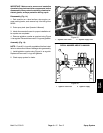
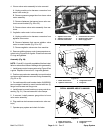
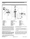
IMPORTANT: The agitation valve motor may have a
fuse for circuit protection. Make sure that correct
fuse is installed in the in--line fuse holder located in
the boom valve motor harness.
The agitation switch on the operator spray console is
used to energize the agitation valve motor and open the
valve. The open agitation valve allows system flow to
reach the three (3) agitationnozzles locatedin the spray
tank. Two (2) styles of agitation valve motors have been
used on Multi Pro 5700--D machines. Both of these mo-
tor styles are shown in Figure 27.
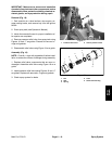
IMPORTANT: Make sure to remove and neutralize
chemicals from spray components before disas-
sembly. Wear protective clothing, chemical resist-
ant gloves, and eye protection during repair.
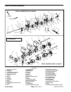
Disassembly (Fig. 27)
1. Remove agitation valve motor assembly from ma-
chine (see Spray Control Assembly in this section).
2. Disassemble agitation valve motor assembly as
needed using Figure 27as a guide. Discard all removed
O--rings and gaskets.
3. See Boom and Agitation Valve Motors in this section
for disassembly and assembly information of the agita-
tion valve motor.
Assembly (Fig. 27)
NOTE: Coatall O--rings with vegetable oil before instal-
lation to reducethe chanceof damage duringassembly.
1. Assemble agitation valve motor assembly using Fig-
ure 27 as a guide. Replace all removed O--rings.
2. Install agitation valve motor assembly on machine
(see Spray Control Assembly in this section).
3. Operate spray system and check for leaks.
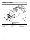
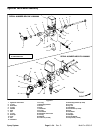
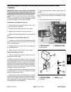
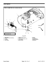
1. Agitation valve motor
2. Agitation supply hose
3. LH boom valve motor
4. Center boom valve motor
5. RH boom valve motor
Figure 28
1
2
5
4
3
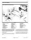
SERIAL NUMBER BELOW 310000000
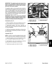
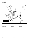
Figure 29
1
2
5
4
3
SERIAL NUMBER ABOVE 310000000
1. Agitation valve motor
2. Agitation supply hose
3. LH boom valve motor
4. Center boom valve moto
5. RH boom valve motor
Spray
System