


Rev. D
Multi Pro 5700--D Page 6 -- 29 Spray System
Boom and Agitation Valve Motor Service (Machines with Serial Numbers Above
310000000)
IMPORTANT: Make sure to remove and neutralize
chemicals fromspray components before valvemo-
tor disassembly.Wear protective clothing,chemical
resistant gloves and eye protection during repair.
NOTE: There are limited replacement parts available
for boom and agitation valve motor assemblies. Check
your parts catalog for parts that are available.
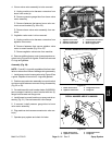
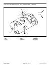
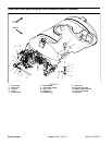
Valve Motor Cover Removal (Fig. 34)
1. Loosen three (3) screws that secure valve motor
cover to valve motor assembly.
2. Carefully lift and rotate cover from valve motor.
3. Unplug wire connections and remove cover.
4. Makesure thatall screwsthat secure valvemotor are
tight.
Valve Motor Cover Installation (Fig. 34)
1. Connect cover wires to motor wires. Make sure that
cover wire color is the same as the motor wire color
when connecting wires.
2. Carefully rotate cover onto valve motor taking care
to not damage wires.
3. Tighten screws to secure cover to valve motor.
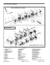
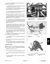
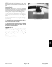
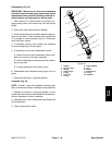
Piston Valve Service (Fig. 35)
1. Remove hosebarb from bottom of valve motor to al-
low access to piston valve.
2. Make sure that valve is closed. If valve is not closed,
spring above piston valve will be under compression
and may damagevalve motor or piston valve during dis-
assembly. End of piston valve will extend into bottom of
valve motor housing when valve is closed. If necessary,
reconnect motor to machine wire harness and close
valve before removing piston valve.
3. Use 3mm allen wrench to loosen and remove piston
valve assembly from valve motor. Locate and retrieve
spring from above piston valve.
4. Inspectseals on piston valve assembly.O--ring in top
groove ofpiston valve assembly is available separately.
If lower two (2) seals in piston valve are worn or dam-
aged, replace piston valve assembly. The piston valve
is not designed to be disassembled.
5. Apply silicone grease to seals on piston valve as-
sembly.
6. Position spring into valve motor housing. Use 3mm
allen wrench to secure piston v alve assembly to valve
motor.
7. Secure hosebarb to bottom of valve motor.
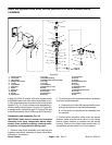
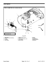
1. Valve motor assembly
2. Valve motor cover
3. Wire connector
4. Socket screw (4 used)
5. Phillips screw (2 used)
Figure 34
1
2
5
4
3
3
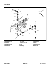
1. Valve motor assembly
2. Piston valve assembly
3. Valve seal
4. Spring
5. Valve motor cover
Figure 35
2
1
3
4
5
Spray
System