


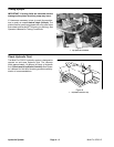
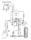
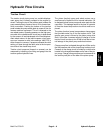

Spray Pump Drive Circuit
A single section gear pump is coupled directly to the pis-
ton (traction) pump. The gear pump supplies hydraulic
flow to the steering control valve and the spray pump
drive hydraulic motor. Gear pump hydraulic flow is deliv-
ered to the two circuits through a flow divider with the
steering circuit having priority. The gear pump takes its
suction from the hydraulic reservoir. Spray pump drive
circuit pressure is limited by an adjustable relief valve lo-
cated on the outside of the piston (traction) pump.
Spray pump drive circuit hydraulic flow and pressure
can be monitored at the outlet of the gear pump.
Hydraulic flow control for the spray pump drive hydraulic
motor is completed by the Pulse Width Modulated
(PWM) Valve. The PWM Valve consists of an electric so-
lenoid valve that allows the operator to adjust hydraulic
flow to the spray pump motor. The spray pump on/off
and application rate (increase/decrease) switches are
used to adjust electrical current to the PWM Valve sole-
noid.
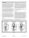
With the engine running and the spray pump switch in
the OFF position, the solenoid valve in the PWM Valve
is not energized. All gear pump flow to the PWM Valve
is directed out the EX port of the PWM Valve, to the oil
cooler, and returns to the hydraulic oil reservoir. The
spray pump hydraulic motor receives no hydraulic flow
so the spray system pump is not rotated and no spray
system flow is available.
With the engine running and the spray pump switch in
the ON position, the solenoid valve in the PWM Valve is
energized. Based on available current (mA) from the
spray pump application rate (increase/decrease)
switch, the solenoid spool valve in the PWM Valve di-
rects some gear pump flow out the CF port to the spray
pump hydraulic motor. This hydraulic flow causes the
motor to rotate the spray system pump for spray system
operation. Gear pump hydraulic flow in excess of PWM
solenoid spool valve setting is directed out the EX port
of the PWM Valve, to the oil cooler, and returns to the hy-
draulic oil reservoir.
The spray pump application rate (increase/decrease)
switch allows the operator to adjust electrical current to
the PWM Valve solenoid. Higher current (rate increase)
to the PWM Valve solenoid increases hydraulic flow to
the spray pump motor and results in a higher spray
pump speed with more spray system output/pressure.
Lower current (rate decrease) to the PWM Valve sole-
noid decreases hydraulic flow to the spray pump motor
and results in a lower spray pump speed with less spray
system output/pressure.
NOTE: Correct operation of the PWM Valve depends
on precision manufacturer’s assembly and adjustment.
No disassembly or adjustment of the PWM Valve is rec-
ommended.
Hydraulic
System
Multi Pro 5700–D Page 4 – 11 Hydraulic System