


Rev. C
Multi Pro 5700--D
Page 5 -- 28
Electrical System
Traction Speed Sensor
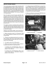
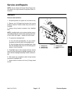
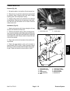
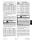
Removal (Fig. 45)
1. Locate speed sensor on right side wheel motor. Dis-
connect speed sensor from machine wire harness.
2. Loosen lock nut and remove speed sensor from
wheel motor.
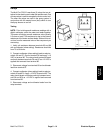
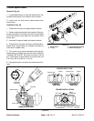
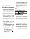
Installation (Fig. 45)
1. Thread lock nut fully onto speed sensor threads.
2. Center a wheel motor piston in the center of the sen-
sor port (see Sensor Port Viewin Fig.46). Use a suitable
tool to feel when a motor piston is in the center of the
sensor port.
3. Lubricate O-ring and install onto sensor threads.
4. Thread sensor into port until sensor contacts piston.
Rotate motor output shaft one complete revolution to
make sure it rotates freely.
5. Turn sensor out (counter-clockwise) until angle be-
tween sensor orientation grooves and motor centerline
is between 90
o
and 93
o
, then back out sensor one full
turn. Hold sensor at this position and torque lock nut
from 75 to 125 in-lb (8.5 to 14.1 N--m).
6. Plug speed sensor connector into machine wire har-
ness.
1. Speed sensor
2. O--ring
3. RH wheel motor housin
g
4. Motor piston group
Figure 45
1
2
3
4
Figure 46
SENSOR SIDE VIEW
Speed Sensor
Lock Nut
Piston
Orientation
Grooves
SENSOR PORT VIEW
Sensor Port
Sensor Port
Piston
POSITION POSITION
INCORRECT
CORRECT
Piston
SENSOR INSTALLATION
Motor
Centerline
Orientation
Grooves
90
o
to 93
o