


Traction Circuit Relief Pressure Test
1. Make sure hydraulic oil is at normal operating tem-
perature by operating the machine for approximately 10
minutes. Make sure the hydraulic tank is full.
2. Park machine on a level surface, stop engine, en-
gage parking brake, and remove key from the ignition
switch. After turning engine off, operate all hydraulic
controls to relieve hydraulic system pressure.
CAUTION
of this section.
Prevent personal injury and/or damage to equip-
ment. Read all WARNINGS, CAUTIONS, and Pre-
cautions for Hydraulic Testing at the beginning
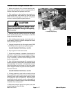
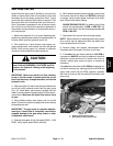
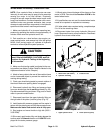
3. Clean and disconnect hydraulic pressure hose from
piston pump fitting on right side of pump for function to
be checked (Fig. 14):
Forward pressure hose is upper hose
Reverse pressure hose is lower hose
4. Install T–connector with 10,000 PSI test gauge be-
tween the piston pump fitting and the disconnected
hose.
5. After installing pressure gauge, start engine and run
at idle speed. Check for hydraulic leakage and correct
before proceeding with test.
6. Operate the engine at high idle speed (3050 – 3150
RPM).
CAUTION
and obstructions.
Move machine to an open area, away from people
7. Drive machine to an open area and engage the park-
ing brake.
8. Sit on seat, apply brakes fully, and slowly depress the
traction pedal in the appropriate direction (forward or re-
verse). While pushing traction pedal, look at pressure
reading on gauge:
GAUGE READING TO BE:
Forward: maximum of 4000 PSI
Reverse: maximum of 4000 PSI
9. Release traction pedal and stop engine. Record test
results.
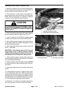
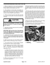
10.If traction pressure is too low, inspect traction pump
relief valves (Fig. 15). Clean or replace valves as neces-
sary. These cartridge type valves are factory set, and
are not adjustable. If relief valves are in good condition,
traction pump or wheel motors should be suspected of
wear and inefficiency.
11. Disconnect pressure gauge from machine and re-
connect hydraulic hose.
1
2
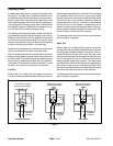
Figure 14
1. Forward pressure hose 2. Reverse pressure hose
1
2
Figure 15
1. Forward relief valve 2. Reverse relief valve
Hydraulic System Page 4 – 18 Multi Pro 5700–D