


Multi Pro 5700--D Hydraulic SystemPage 4 -- 53
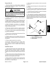
Removal (Fig. 52)
1. Park the machine on a level surface, engage the
parking brake, and stop the engine. Remove the key
from the ignition switch.
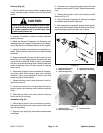
CAUTION
Rotate steering wheeland depress traction ped-
al in both forward and reverse to relieve hydrau-
lic system pressure and to avoid injury from
pressurized hydraulic oil.
2. Operate all hydraulic controls to relieve hydraulic
system pressure.
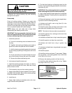
3. Read the General Precautions for Removing and
Installing Hydraulic System Components at the begin-
ning of the Service and Repairs section of this chapter.
4. Label all hydraulic connections for reassembly.
Clean hydraulic hose ends prior to disconnecting the
hoses from steering cylinder.
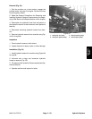
5. Disconnect hydraulic hoses from steering cylinder
(Fig. 53). Allow hoses to drain into a suitable container.
6. Put caps or plugson disconnectedhoses andfittings
to prevent contamination.
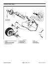
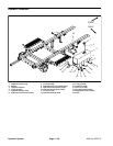
7. Remove lock nut that secures the barrel end of the
steering cylinder to the front axle.
8. Remove cotter pin and hex slotted nut that secure
the shaft end of the steering cylinder to the left side front
axle spindle.
9. Remove steering cylinder from machine.
10.If ball joint requires removal from cylinder shaft,
count number of revolutions it takes to remove from
shaft so ball joint can be re--installed without affecting
steering.
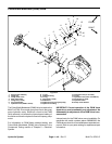
Installation (Fig. 52)
1. If ball joint was removed from cylinder shaft, apply
antiseize lubricant to threads of cylinder shaft. Install
ball joint onto shaft the same number of revolutions
needed to remove ball joint. Secure ball joint with jam
nut.
2. Place rod end seal on cylinder shaft ball joint. Insert
rod ends of cylinder down into attachment points on the
left side front axle spindle and front axle.
3. Secure shaft end of cylinder to the front axle spindle
with slotted hex nut. Torque hex nut from 20 to 25 ft--lb
(27to34N--m).Installcotterpin.
4. Secure barrel end of cylinder to the front axle with
locking nut.
5. Remove caps and plugs from disconnected hoses
and fittings.
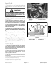
6. Lubricate new O--rings and connect hydraulic hoses
to steering cylinder (Fig. 53). Tighten hose connections.
7. Check fluid level in hydraulic oil reservoir and adjust
as required (see Operator’s Manual).
8. After assembly is completed, operate steering cylin-
der to verify that hydraulic hoses and fittings are not con-
tacted by anything and that there are no leaks. Also,
makesure that aclockwise rotation ofthe steeringwheel
makes a right turn.
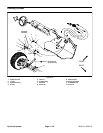
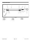
1. Hose from steering control R port
2. Hose from steering control L port
3. Steering cylinder
Figure 53
1
3
2
Hydraulic
System