


Steering Circuit
A single section gear pump is coupled to the piston (trac-
tion) pump. The gear pump supplies hydraulic flow to
the steering control valve and the spray pump drive hy-
draulic motor. Pump hydraulic flow is delivered to the
two circuits through a flow divider with the steering cir-
cuit having priority. The gear pump takes its suction from
the hydraulic reservoir. Steering circuit pressure is limit-
ed by a relief valve located in the gear pump.
The steering control valve includes a check valve that al-
lows steering operation when the engine is not running.
Steering wheel rotation with the engine off causes oil
flow from the steering control gerotor. The check valve
opens in this situation to allow oil flow from the steering
control to the steering cylinder in a closed loop.
Hydraulic flow and pressure to the steering control valve
can be monitored at the outlet of the gear pump.
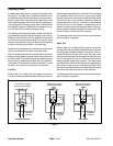
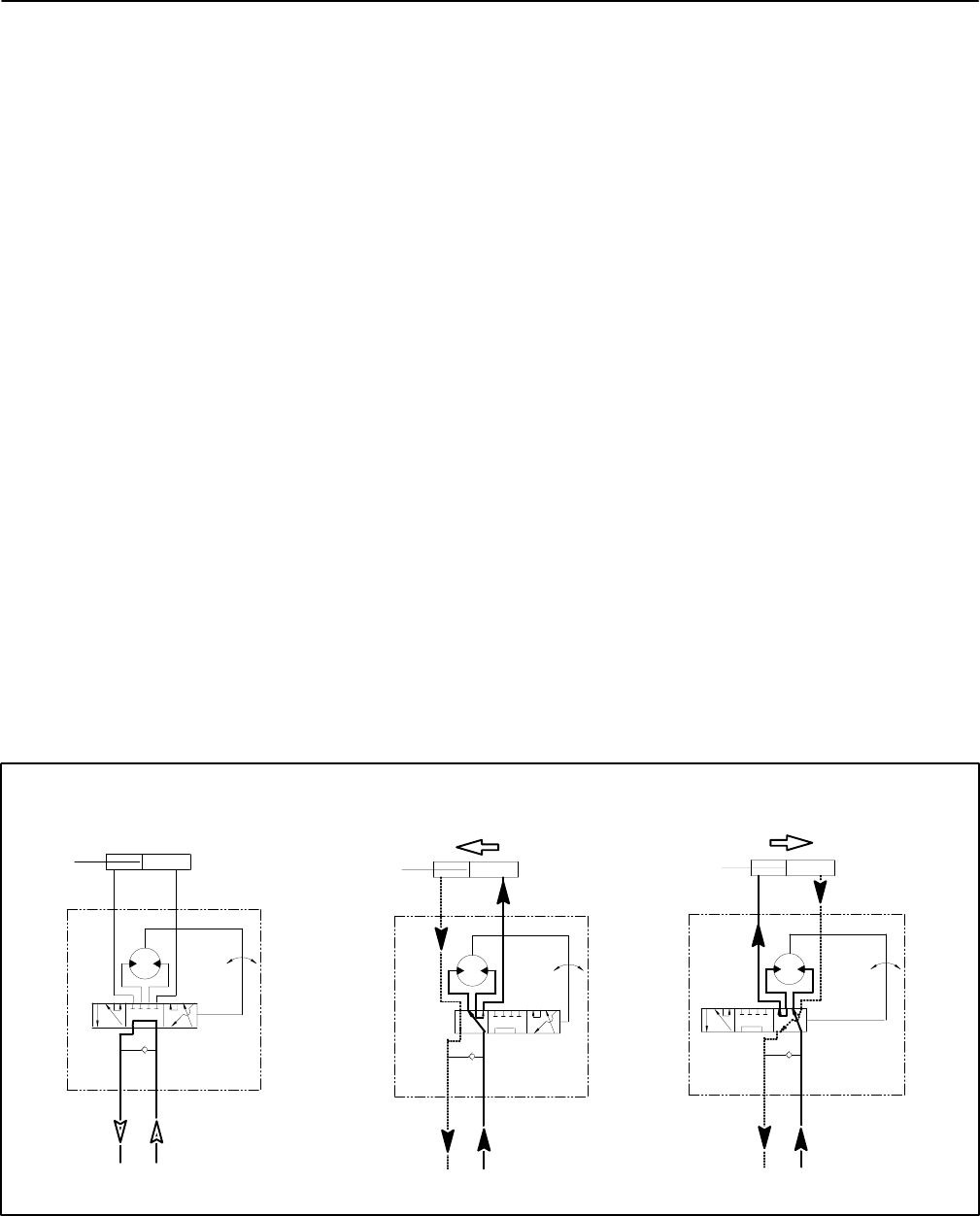
With the steering wheel in the neutral position and the
engine running, gear pump flow enters the steering con-
trol valve (port P) and goes through the steering control
spool valve, by–passing the rotary meter (V1) and steer-
ing cylinder. Flow leaves the control valve (port T), to the
oil cooler, and returns to the hydraulic oil reservoir.
Left Turn
When a left turn is made with the engine running, the
turning of the steering wheel positions the spool valve so
that flow goes through the top of the spool. Flow entering
the steering control valve from the gear pump goes
through the spool and is routed through the rotary meter
(V1) and out the L port. Pressure extends the steering
cylinder piston for a left turn. The rotary meter ensures
that the oil flow to the cylinder is proportional to the
amount of the turning on the steering wheel. Fluid leav-
ing the cylinder flows back through the spool valve, then
to the oil cooler and returns to the reservoir.
The steering control valve returns to the neutral position
when turning is completed.
Right Turn
When a right turn is made with the engine running, the
turning of the steering wheel positions the spool valve so
that flow goes through the bottom of the spool. Flow en-
tering the steering control valve from the gear pump
goes through the spool and is routed through rotary me-
ter (V1) but goes out port R. Pressure contracts the
steering cylinder piston for a right turn. The rotary meter
ensures that the oil flow to the cylinder is proportional to
the amount of the turning on the steering wheel. Fluid
leaving the cylinder flows back through the spool valve,
then to the oil cooler and returns to the reservoir.
The steering control valve returns to the neutral position
when turning is completed.
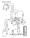
STEERING CYLINDER
STEERING CYLINDER
STEERING CYLINDER
NO PISTON MOVEMENT
PISTON MOVEMENT
PISTON MOVEMENT
R L
T P
STEERING
CONTROL
STEERING
T
R
P
L
CONTROL
STEERING
T
R
P
L
CONTROL
NEUTRAL POSITION
LEFT TURN
RIGHT TURN
Figure 9
Hydraulic System Page 4 – 10 Multi Pro 5700–D