


Rev. C
Multi Pro 5700--D
Page 5 -- 14
Electrical System
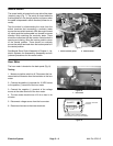
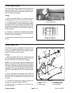
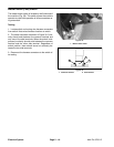
Traction Speed Sensor
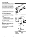
The traction speed sensor is attached to the right side
rear wheel motor (Fig. 21). The sensor provides ground
speed information for two (2) options: the Pro Control
Electronics and the speedometer kit. It uses a magneti-
cally based, Hall Effect integrated circuit. As the piston
group in the wheel motor turns, the sensor accurately
senses the movement ofthe pistons passing the sensor.
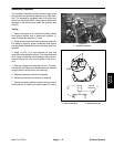
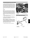
The red connector wire (connector terminal A) is the
positive lead, the black wire (terminal C) is the ground
lead, and the white wire (terminal B) is the signal output.
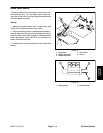
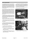
Testing
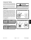
1. Make sure ignition switch is off. Remove speed sen-
sor from machine (see Traction Speed Sensor Removal
in the Service and Repair Section of this Chapter).
IMPORTANT: Incorrect jumper wire connections
during testing can damage the sensor.
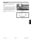
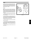
2. Using a +12 VDC battery, a multimeter, a 1K ohm re-
sistor and appropriate jumperwires, connectthe battery
and multimeter to the speed sensor using Figure 22 as
a guide.
3. Set multimeter to DC volts setting.
4. Themultimeter should display verylow voltage when
a metal objectis held near the sensor tip. The multimeter
should display battery voltage when the metal object is
moved away from the sensor tip.
5. After sensor testing is complete, remove jumper
wires, resistor and multimeter leads from sensor con-
nector.
IMPORTANT: W hen replacing the sensor, see Trac-
tion Speed Sensor Installation in the Service and
Repair Section of this chapter.
6. Reinstall speed sensor into wheel motor (see Trac-
tion Speed SensorInstallation inthe Service andRepair
Section of this Chapter). Reconnect speed sensor to
machine wire harness.
1. Speed sensor
2. O--ring
3. RH wheel motor housing
4. Motor piston group
Figure 21
1
2
3
4
1. Speed sensor
2. Sensor tip
3. Lock nut
4. Sensor connector
5. Red wire
6. White wire
7. Black wire
Figure 22
--
+
12 VDC
7
4
2
3
1
6
1K ohm
resistor
5