


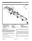

Boom Actuator Service (Machines with Serial Numbers Above 260000000)
IMPORTANT: Do not dismantle, repair or modify the
boom actuator. Internal components are not avail
-
able for the actuator. If an actuator is damaged or
worn, replace actuator.
CAUTION
During and after operation, the actuator may be
tuator to cool before working on it.
very hot. To avoid possible burns, allow the ac-
Actuator Circuit Protection
Each boom actuator is protected internally by a thermal
circuit breaker. In case of actuator overheating, the ther
-
mal breaker will trip, causing the actuator to cease func-
tioning. Once the actuator cools to appropriate
operating temperature, the actuator thermal breaker will
reset to allow actuator operation to resume.
A separate 30 amp thermal breaker also protects each
boom actuator circuit. These thermal breakers are lo
-
cated at the machine fuse panel and will prevent circuit
operation if overloaded. The thermal breakers reset au
-
tomatically.
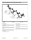
Actuator Freeplay Inspection
Over time, actuator operation may be affected by air
captured in the reservoir oil. An excessive amount of air
in the actuator oil will allow excessive actuator freeplay.
Excessive freeplay will allow spray boom bouncing
when driving over severe terrain.
Measure actuator freeplay using the following proce-
dure:
1. Move the vehicle to an open area and lower the spray
booms to the spray position.
2. Lift up on the boom at the last triangular gusset with
a 25 pound (11.4 kg) force. Support boom in that posi
-
tion.
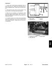
3. Using a non–permanent felt tipped marker, mark the
cylinder rod at the outside of the cylinder seal.
4. Release the spray boom and allow it to return to the
spray (fully lowered) position.
5. Determine the actuator freeplay by measuring the
distance from the mark on the cylinder rod to the cylinder
seal. The freeplay should be less than 0.100” (2.5 mm).
If excessive freeplay is found, bleed air from actuator.
Actuator Air Bleeding
If actuator freeplay is excessive, air bleeding of the ac-
tuator should be performed using the following proce-
dure:
1. Thoroughly clean the exterior of actuator to prevent
contaminates from entering the actuator.
2. Make sure that the actuator cylinder is fully retracted.
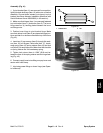
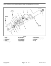
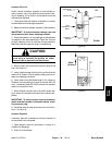
IMPORTANT: To prevent actuator damage, use vise
with protective jaws when clamping actuator.
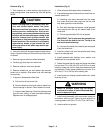
3. Place the actuator in a vise making sure that actuator
is clamped in the area identified in Figure 49. Use just
enough clamping force to hold the housing securely.
Make sure that the reservoir plug is orientated up.
CAUTION
The actuator reservoir is pressurized. If the res-
ervoir plug is removed too quickly, oil under
pressure can be ejected from the actuator.
4. Slowly loosen and remove the reservoir plug at the
top of the reservoir.
5. Using a light through the plug hole, confirm that the
reservoir oil is clear. If the oil appears milky, air is en
-
trained in the reservoir oil. Keep the actuator vertical
with the plug removed for approximately 15 minutes to
allow the air to separate from the oil.
6. When oil appears clear, use a 12 volt DC power sup-
ply to power the actuator and extend the cylinder com-
pletely.
IMPORTANT: To ensure proper reservoir pressure,
make sure that cylinder is extended before instal
-
ling reservoir plug.
7. Install the reservoir plug and torque from 45 to 60 in–
lb (5.1 to 6.8 N–m).
8. If reservoir oil was milky, use power supply to con-
tract and extend the actuator cylinder 3 times. Repeat
steps 2 through 7 until oil is clear.
9. When actuator oil is clear and plug has been
installed, use power supply to fully contract the actuator
cylinder. Remove actuator from vise and install on ma
-
chine.
Spray System
Page 6 – 48
Rev. A
Multi Pro 5700–D