


Multi Pro 5700–D
Page 5 – 10
Electrical System
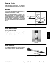
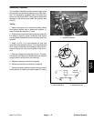
Cruise Control Switch
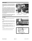
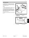
The cruise control switch is positioned on the dash panel
above the ignition switch (Fig. 12). This switch ener-
gizes the cruise control coil to allow the operator to main-
tain a constant ground speed.
Testing
1. Make sure ignition switch is off. Locate switch and
unplug machine wire harness connector from switch.
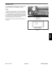
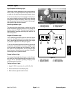
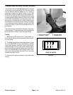
2. The switch terminals are marked as shown in Figure
13. In the ON position, continuity should exist between
terminals 2 and 3. In the momentary SET position, conti-
nuity should exist between terminals 5 and 6. In the OFF
position, there should be no continuity between any
switch terminals.
3. Terminals 7 (–) and 8 (+) are used for the indicator
light in the switch. The light should be illuminated when
the switch is in the ON position.
4. Reconnect the harness connector to the switch after
testing.
1. Cruise control switch
Figure 12
1
Figure 13
BACK OF SWITCH
823
756
Cruise Control Coil
The cruise control coil is energized by the cruise control
switch. The energized coil becomes a magnet to hold
the traction pedal in position and maintains ground
speed for accurate sprayer operation.
Testing
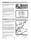
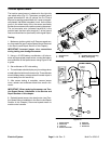
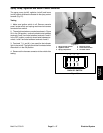
1. Make sure ignition switch is off. Locate control coil
next to traction pedal under the floorboard (Fig. 14). Un-
plug coil connector from machine wire harness.
NOTE: Prior to taking small resistance readings with a
digital multi meter, short the meter test leads together.
The meter will display a small resistance value (usually
0.5 ohms or less). This resistance is due to the internal
resistance of the meter and test leads. Subtract this val-
ue from from the measured value of the coil you are test-
ing.
2. Using a multimeter (ohms setting), verify control coil
resistance between the terminals of the connector and
the frame of the coil. Resistance should be from 3.6 to
4.0 ohms.
3. If coil does not engage when voltage is applied or coil
resistance is incorrect, replace control coil.
4. Reconnect the coil connector to the machine har-
ness after testing.
1. Cruise control coil
2. Plate
3. Traction pedal
4. Cap screw (4 used)
5. Lock washer (4 used)
6. Hex nut (4 used)
Figure 14
1
2
3
4
6
5