


Rev. D
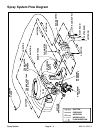
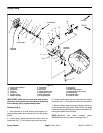
Multi Pro 5700--DPage 6 -- 10Spray System
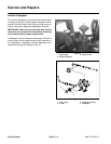
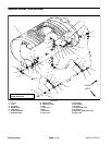
Spray Pump
1. Spray pump assembly
2. Flange nut
3. Square key
4. Lock nut
5. Pump hub
6. Coupler spacer
7. Rubber coupling
8. Flat washer
9. Cap screw
10. Set screw
11. Hydraulic motor hub
12. Flange head screw
13. Rear guard plate
14. Front guard plate
15. Flange nut
16. PWM Valve
17. Pump mount bracket
18. Flange head screw (4 used)
19. Woodruff key
20. Hydraulic motor
21. U--bolt (2 used)
Figure 6
FRONT
RIGHT
1
2
3
4
5
6
8
10
9
12
13
14
15
17
7
11
6
8
9
4
2
10
Loctite #242
Loctite #242
Antiseize
Lubricant
Antiseize
Lubricant
19
18
16
20
21
IMPORTANT: Make sure to neutralize and remove
chemicals from pump and hoses before loosening
and removing spray system components.
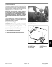
Removal (Fig. 6)
1. Park machine on a level surface, stop engine, en-
gage parking brake, and remove key from the ignition
switch.
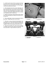
2. Loosen hose clamp that secures suction hose to
hose barb (Fig. 7). Pull suction hose from hose barb.
3. Loosen hose clamp that secures pressure hose to
hose barb (Fig. 7). Pull pressure hose from hose barb.
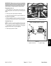
4. Remove flange head screw and flange nut that se-
cure front and rear guard plate. Remove four (4) flange
nuts thatretain guard plates to pumpmount bracket. Re-
move guard plates from machine.
NOTE: Machines with serial numbers above
290000400 use two (2) rubber couplings (item 7).