


Traction Circuit Charge Pressure Test
1. Make sure hydraulic oil is at normal operating tem-
perature by operating the machine for approximately 10
minutes. Make sure the hydraulic tank is full.
2. Park machine on a level surface, stop engine, en-
gage parking brake, and remove key from the ignition
switch. After turning engine off, operate all hydraulic
controls to relieve hydraulic system pressure.
CAUTION
of this section.
Prevent personal injury and/or damage to equip-
ment. Read all WARNINGS, CAUTIONS, and Pre-
cautions for Hydraulic Testing at the beginning
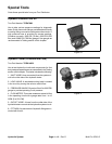
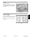
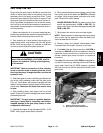
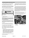
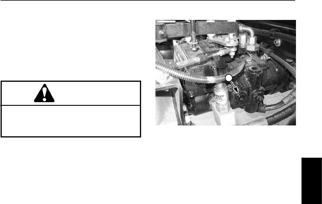
3. Remove plug from auxiliary test port on left side of
piston (traction) pump (Fig. 13). Connect a 1000 PSI
gauge into auxiliary test port.
4. After installing pressure gauge, start engine and run
at idle speed. Check for hydraulic leakage and correct
before proceeding with test.
5. Operate the engine at high idle engine speed (3050
– 3150 RPM) with no load on the hydraulic system.
GAUGE READING TO BE 250 to 300 PSI.
6. Stop engine and record test results.
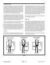
7. If there is no pressure, or pressure is low, check for
restriction in pump suction line. Also, inspect charge re-
lief valve located in charge pump adapter on piston
pump. If necessary, check for internal damage or worn
parts in charge pump.
8. Also, with the pressure gauge still connected to the
auxiliary test port on piston pump, take a gauge reading
while operating the machine in forward and reverse.
Start the engine and put throttle at high idle engine
speed. Apply the brakes and push the traction pedal for-
ward, then reverse.
GAUGE READING TO BE 250 to 300 PSI.
9. If charge pressure is good under no load, but drops
below specification when under traction load, the piston
(traction) pump and/or traction wheel motor(s) should
be suspected of wear and inefficiency. When the piston
pump and/or traction motor(s) are worn or damaged, the
charge pump is not able to keep up with internal leakage
in traction circuit components.
10.Disconnect pressure gauge from piston pump and
reinstall plug to auxiliary test port.
Multi Pro 5700–D Page 4 – 17
1
Figure 13
1. Auxiliary test port plug
Hydraulic System
Hydraulic
System