


Multi Pro 5700–DChassis
Page 7 – 10
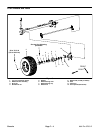
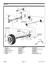
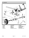
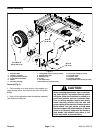
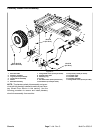
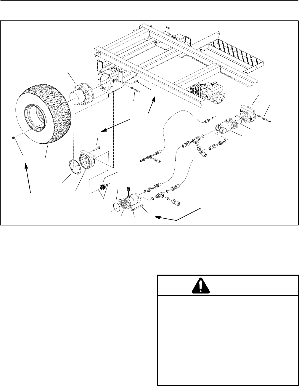
Brake Assembly
1. RH brake cable
2. Planetary assembly
3. Lug nut (8 used per wheel)
4. Tire and wheel assembly
5. Gasket
6. RH brake assembl
y
7. Flange head screw (4 used per brake)
8. Splined brake shaft
9. Retaining ring
10. O–ring
11. RH wheel motor
12. Flat washer (2 used per motor)
13. Cap screw (2 used per motor)
14. LH wheel motor
15. LH brake cable
16. LH brake assembly
17. Flange head screw (6 used per side)
Figure 6
70 to 90 ft–lb
(95 to 122 N–m)
60 ft–lb
(81 N–m)
1
2
3
4
5
12
13
14
15
16
6
7
8
9
10
11
10
17
60 ft–lb
(81 N–m)
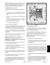
Removal (Fig. 6)
1. Park machine on a level surface, stop engine, en-
gage parking brake, and remove key from the ignition
switch.
2. Drain oil from planetary wheel drive/brake assembly
(see Operator’s Manual).
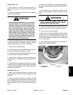
CAUTION
When changing attachments, tires, or perform-
ing other service, use correct blocks, hoists,
and jacks. Make sure machine is parked on a
solid, level surface such as a concrete floor.
Prior to raising machine, remove any attach-
ments that may interfere with the safe and
proper raising of the machine. Always chock or
block wheels. Use jack stands or solid wood
blocks to support the raised machine. If the ma-
chine is not properly supported by blocks or
jack stands, the machine may move or fall,
which may result in personal injury.