


Reference
99
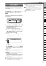
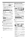
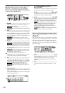
COUNTERMODELING
INSERT
EFFECT
EQ
MASTER
EFFECT/
AUX SEND
FINAL
EFFECT
BOUNCECDTUNERRHYTHM
INPUT/
OUTPUT/
SOLO
SYSTEM/
USB
TRACKSONG
IN/LOC1,
…END/LOC4
MARKSCENE
AUTO
PUNCH
TRIGGERSCRUB
METER/
TRACK VIEW
UNDO LOOP
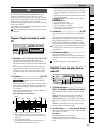
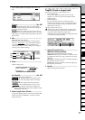
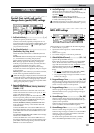
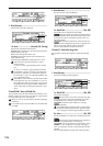
InEq1–4: Adjust the EQ for inputs 1–
4
Here you can apply EQ (equalization) to the analog inputs
from the [INPUT 1/GUITAR IN]–[INPUT 4] jacks. Use this
when you want to record the sound with EQ applied.
The EQ is a three-band type, with shelving-type high and
low bands, and a peaking-type mid band with adjustable
center frequency.
The input EQ cannot be applied to the digital input (S/
P DIF IN) or to the rhythm.
The “InEq1–4” tab page settings cannot be paired.
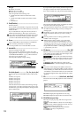
1. InputLevelMeter.................................................
(1, 2, 3, 4/CLP, –8, –18, –42 dB)
Indicates the level of each analog input.
The horizontal axis indicates the channel, and the verti-
cal axis indicates the level.
Inputs that are not selected in the [INPUT/OUTPUT/
SOLO] “Ch1...6” tab page will not be shown here.
2. InputHigh.......... [(Fc=10kHz) –15.0...+15.0 (dB)]
Sets the input high EQ gain. This will adjust the high-
frequency range.
The region above 10 kHz can be boosted/cut over a
range of –15.0 – +15.0 dB.
3. InMidFc.............................. [100Hz...20.0k (Hz)]
Specifies the frequency of the input mid EQ.
The frequency can be adjusted over a range of 100 Hz–
20.0 kHz.
4. InputMid..............................[–15.0...+15.0 (dB)]
Sets the input mid EQ gain. This will adjust the mid-fre-
quency range.
The region specified by InputMid can be boosted/cut
over a range of –15.0 – +15.0 dB.
5. InputLow............[(Fc=100Hz) –15.0...+15.0 (dB)]
Sets the input low EQ gain. This will adjust the low-fre-
quency range.
The region below 100 Hz can be boosted/cut over a
range of –15.0 – +15.0 dB.
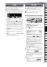
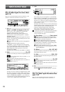
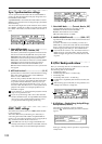
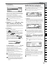
Solo: Select the signal to be soloed
1. SelectSolo .........................................................
[1...6, 7–8...11–12, S1, S2, A1, R1, R2/On, Off]
Switches the solo function on/off.
Only the audio signals for which the “Solo” button is on
will be sent to the monitor LR bus. Use this when you
want to hear only a specific audio channel out of many
channels, or when you want to check the send signal.
The solo signal will be output from the [MONITOR
OUT L/R] jacks and from the [PHONES] jack.
If even one of these solo buttons is “On,” the [INPUT/
OUTPUT/SOLO] key will blink.
On: Solo will be on. Only the corresponding signal
will be heard.
Off: Solo will be off. If any other signal is being
soloed, the corresponding signal will be muted.
1...6: Mixer channel 1–6
7–8...11–12: Mixer channels 7–8...11–12.
S1, S2: Send to master effects 1 and 2
A1: Send to the [AUX OUT] external output jack
R1, R2: Return from master effects 1 and 2
The volume of each signal is set by the corresponding
page or knob. When you select a different signal to be
soloed, the monitor volume may change significantly.
2. ClearAll ............................................................
Turns “Off” all solo signals that are currently turned
“On” by the “SelectSolo” buttons.
3. SoloToMstOut...................................... [On, Off]
Specifies whether the soloed signal(s) will be output
from the [MASTER OUT L/R] jacks. Turn this on if your
monitor system is connected to the [MASTER OUT L/R]
jacks and you want to solo through those jacks.
On: The solo signal(s) will be output
from the [MONITOR OUT L/R] jacks.
Off: The solo signal(s) will be output
from the [MONITOR OUT L/R] jacks and the
[PHONES] jack.
The “On” setting is valid only while you are in the
[INPUT/OUTPUT/SOLO] tab page. When you leave
this page, the setting will automatically be turned
“Off.”
1
324
5
1
2
3
INPUT/
OUTPUT/
SOLO