


Introduction
7
Parts and their functionObjects in the display and
their function
Basic operationPreparationsListening to the demo song
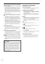
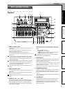
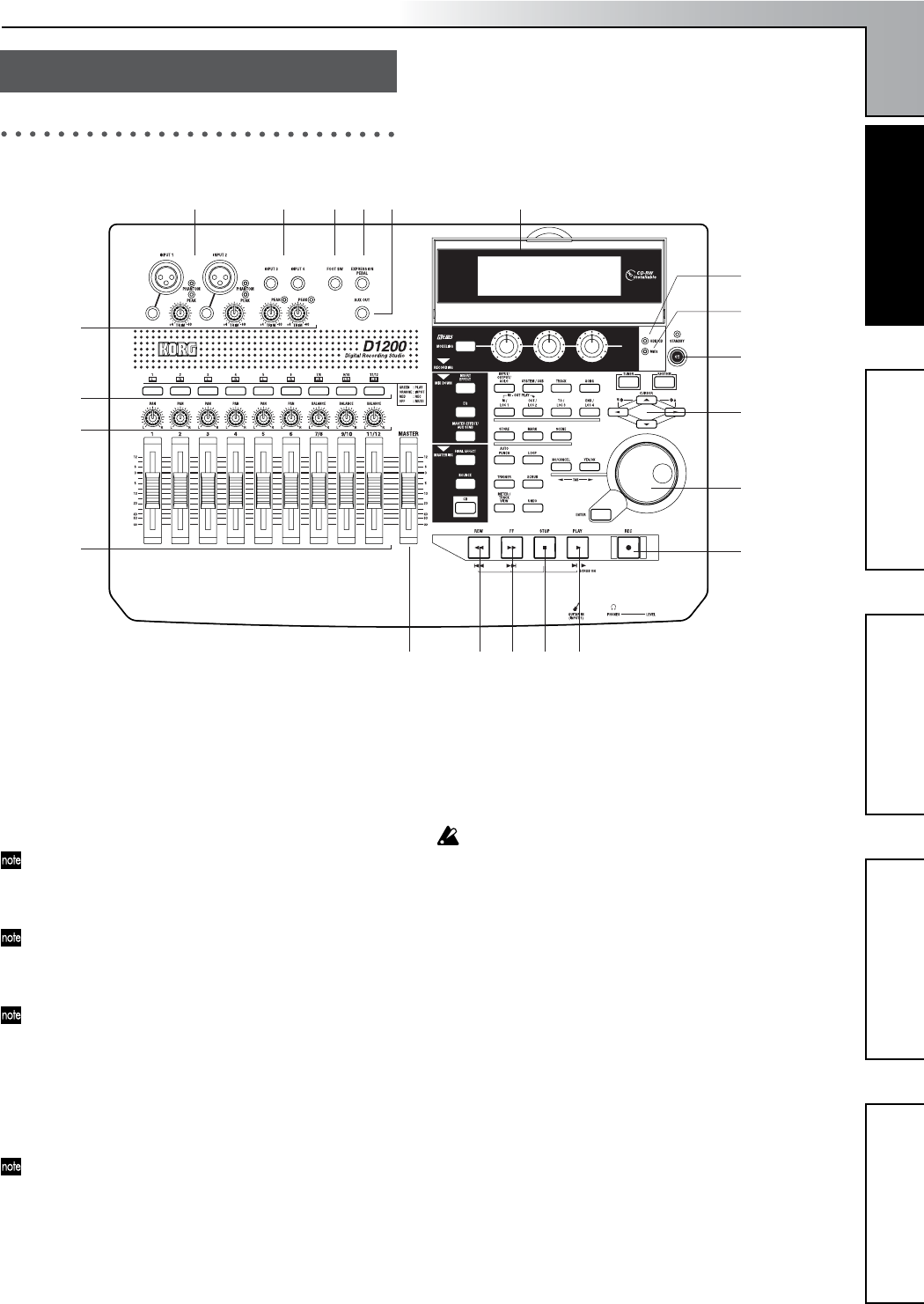
Top panel
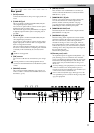
1 [INPUT 1], [INPUT 2] jacks
Use these jacks to input mic/line signals (such as from a
keyboard).
You can use either XLR jacks or TRS phone jacks, and
both sets of jacks are balanced.
Unbalanced phone plugs can also be connected.
The XLR jacks can supply +48 V phantom power to con-
denser mics.
If you connect a plug to the phone jack, no signal can be
input from the corresponding XLR jack. If you want to
use the XLR jack, disconnect any plug from the corre-
sponding phone jack.
If you connect a plug to the [GUITAR IN] jack, no signal
can be input from the [INPUT 1] jack. If you want to in-
put a signal from the [INPUT 1] jack, disconnect any
plug from the [GUITAR IN] jack.
These TRS phone jacks do not individually allow stereo
input.
2 [INPUT 3], [INPUT 4] jacks
Use these jacks to input mic/line signals (such as from a
keyboard).
These are balanced TRS phone jacks. Unbalanced phone
plugs can also be connected.
These TRS phone jacks do not individually allow stereo
input.
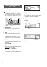
3 [TRIM] knob: –60...–10....+4 dBu
These knobs adjust the input level. Input level calibra-
tion marks are printed on the panel. Adjust the [TRIM]
knobs so that the peak indicators (the LEDs near each
knob) light when the input level of the connected instru-
ment or device is loudest.
Although the input level will depend on the device or
performance, here are some guidelines for setting these
knobs.
–60 – –40 dBu:
mic input
–30 dBu:
guitar or bass guitar
–10 dBu:
CD player or other consumer audio device
+4 dBu:
keyboard or studio equipment
If nothing is connected, you may hear hum or noise
when you raise the [TRIM] knobs.
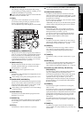
4 [FOOT SW] jack
A foot switch connected to this jack can be used to oper-
ate basic recorder functions when your hands are occu-
pied by playing an instrument.
You can use a foot switch to control play/stop, to start/
stop manual punch-recording, to register a mark, or to
record tap tempo. (
→
p.101)
Connect a PS-1 foot switch (sold separately) to this jack.
5 [EXPRESSION PEDAL] jack
A pedal connected to this jack can be used to control a
specified parameter of an insert effect. This lets you con-
trol an effect in realtime while you perform or record.
(
→
p.44)
Connect an EXP-2 or XVP-10 expression pedal (sold sep-
arately) to this jack.
6 [AUX OUT] jack
This outputs the external send audio signal from each
mixer channel. (The send amount is adjusted in the
[MASTER EFFECT/AUX SEND] “AuxSnd” tab page.)
Connect this jack to an external effect processor.
This is a phone jack.
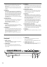
Parts and their function
1
10 11 12 13 14
15
7
2 4 5 6 21
3
8
9
16
17
18
19
20
Parts and their function