


Introduction
11
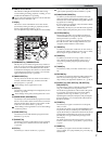
Parts and their functionObjects in the display and
their function
Basic operationPreparationsListening to the demo song
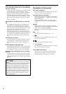
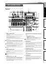
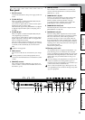
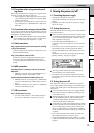
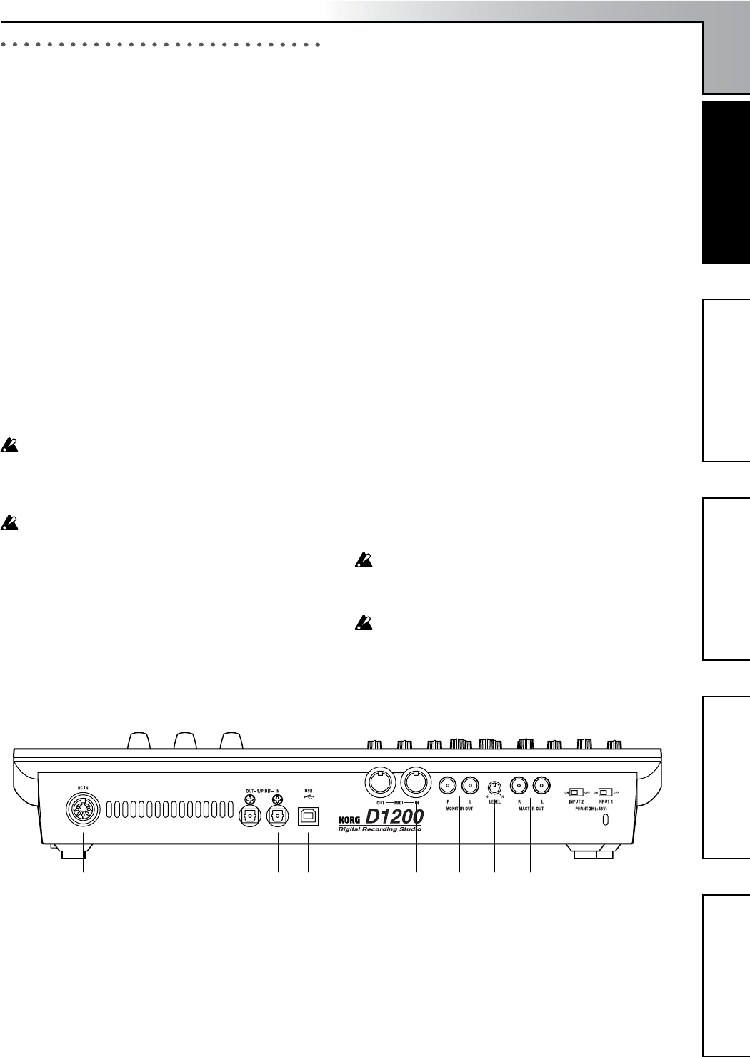
Rear panel
1 [DC IN] connector
Connect the included AC/DC power supply to this con-
nector.
2 [S/P DIF OUT] jack
This is an optical S/P DIF format (IEC60958, EIAJ CP-
1201) digital output jack (stereo).
You can use an optical cable to connect it to the optical
digital input jack of a DAT or MD.
The same audio signal as the [MASTER OUT L/R] jacks
is digitally output from this jack at a sampling rate of
44.1 kHz.
3 [S/P DIF IN] jack
This is an optical S/P DIF format (IEC60958, EIAJ CP-
1201) digital input jack (stereo).
You can use an optical cable to connect it to the optical
digital output jack of a DAT or MD. Use a digital cable
that is no longer than 5 meters.
This jack contains a built-in sampling rate converter. If
the source connected here has a sampling rate of 48 kHz
or 32 kHz, it will automatically be converted to 44.1
kHz.
96 kHz is not supported.
4 [USB] connector
You can use a USB cable to connect this to your compu-
ter.
It is not possible to connect USB peripheral devices
(such as an external hard disk or CD-R/RW drive) to the
D1200.
5 [MIDI OUT] connector
This connector transmits MIDI data. Use it when you
want to control a connected external MIDI device from
the D1200. (→p.79)
6 [MIDI IN] connector
This connector receives MIDI data. Use it when you
want to control the D1200 from a connected external
MIDI device. (→p.79)
7 [MONITOR OUT L/R] jacks
Connect your external monitor system to these jacks.
You can select the bus for monitor output in the
[INPUT/OUTPUT/SOLO] “Monitor” tab page
(→p.100). These jacks output the same signal as the
[PHONES] jack. These are RCA phono jacks.
8 [MONITOR OUT LEVEL] knob
This knob adjusts the volume that is output from the
[MONITOR OUT L/R] jacks.
9 [MASTER OUT L/R] jacks
These are analog audio outputs for the master LR bus
signal that combines the signals of each mixer channel
into a two-channel mix, or the audio signal that is
selected for soloing. To select a solo signal, make set-
tings in the [INPUT/OUTPUT/SOLO] “Solo” tab page.
Connect these jacks to your external monitor system or
recording device. They output the same audio signal as
the [S/P DIF OUT] jack.
These are RCA phono jacks.
10 [Phantom power] switch
+48 V phantom power is supplied to the [INPUT 1, 2]
jacks, allowing you to use condenser mics. Phantom
power is supplied to the balanced XLR jacks, and can be
switched on/off independently for each channel. Turn
on this switch only for channels that are using a con-
denser mic.
You may damage your equipment if you connect or dis-
connect a condenser mic while phantom power is
turned on. Always turn phantom power off before you
connect or disconnect a condenser mic.
Never connect an dynamic type, other type mic or de-
vice if phantom power is turned on. Doing so may dam-
age your equipment.
1 2 3 4 5 6 7 8 9 10
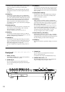
Parts and their function