


Input & Output Patching 109
DM1000 Version 2—Owner’s Manual
9
Input & Output Patching
9 Input & Output Patching
This chapter describes how to patch (assign) signal paths within the DM1000 to its inputs,
outputs, and slot channels
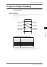
Input Patching
Signals input at INPUT connectors 1–16, 2TR IN DIGITAL connectors 1–2, and Slot I/O
cards are patched to Input Channels for use.
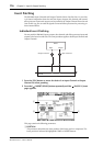
Patch example:
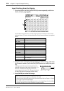
By default, the Input Channels are patched as follows:
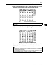
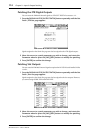
You can change these patches, if you desire. To change input patching, you can either use
the Encoders on the top panel or set the parameters on the display.
Input Channels Input connectors and Slot channels
1–16
INPUT connectors 1–16
17–24
Channels 1–8 of Slot 1
25–32
Channels 1–8 of Slot 2
33–40
Internal Effects Processor 1–4 Outputs 1–2
41/42
2TR DIGITAL IN 1 (L/R)
43/44
2TR DIGITAL IN 2 (L/R)
45–48
OMNI IN connectors 1–4
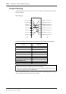
Input Patching
INPUT connector 1
INPUT connector 2
INPUT connector 3
INPUT connector 4
INPUT connector 5
INPUT connector 6
INPUT connector 7
INPUT connector 8
Input Channel 1
Input Channel 2
Input Channel 3
Input Channel 4
Input Channel 5
Input Channel 6
Input Channel 7
Input Channel 8