


Effects Parameters 321
DM1000 Version 2—Owner’s Manual
Appendix
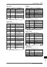
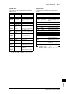
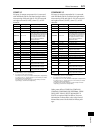
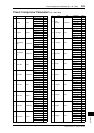
COMP 5.1
Six input, six output compressor for 5.1 surround,
with individual solo for each band, and gain reduc-
tion metering of left and right (L+R), left surround
and right surround (LS+RS), center (C), or LFE
channels.
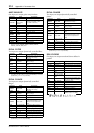
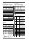
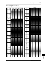
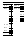
COMPAND 5.1
Six input, six output compander for 5.1 surround,
with individual solo for each band, and gain reduc-
tion metering of left and right (L+R), left surround
and right surround (LS+RS), center (C), or LFE
channels.
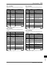
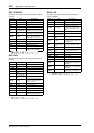
Other preset effects (COMP276, COMP276S,
COMP260, COMP260S, EQUALIZER601, OPEN-
DECK, REV-X HALL, REV-X ROOM, REV-X
PLATE) are optional Add-On Effects. For more
information on these effects, refer to the Owner’s
Manual that came with the Add-On Effects pack-
ages.
Parameter Range Description
LOW GAIN –96.0 to +12.0 dB Low band level
MID GAIN –96.0 to +12.0 dB Mid band level
HI. GAIN –96.0 to +12.0 dB High band level
PRESENCE –10 to +10
For positive values, the threshold
of the high band is lowered and
the threshold of the low band is
increased. For negative values,
the opposite will occur. When
set to 0, all three bands are
affected the same.
THRE. –24.0 to 0.0 dB Compressor threshold
RATIO 1:1 to ∞:1 Compressor ratio
ATTACK 0–120 ms Compressor attack
RELEASE
1
1. 6 ms–46.0 s (fs=44.1 kHz), 5 ms–42.3 s (fs=48 kHz), 3 ms–23.0 s
(fs=88.2 kHz), 3 ms–21.1 s (fs=96 kHz)
Compressor release time
KNEE 0–5 Compressor knee
LOOKUP 0.0–100.0 ms Lookup delay
KEY LINK
2
2. 5.1: Key-in’s of all inputs are linked
5.0: Key-in’s of L, C, R, LS, and RS are linked (LFE is independent)
3+2: Key-in’s of L, C, and R, and key-in's of LS and RS, are linked
respectively (LFE is independent)
2+2: Key-in’s of L and R, and key-in's of LS and RS, are linked
respectively (C and LFE are independent)
Key-in linking
L–M XOVR 21.2 Hz–8.00 kHz Low/mid crossover frequency
M–H XOVR 21.2 Hz–8.00 kHz Mid/high crossover frequency
SLOPE –6 to –12 dB Filter slope
CEILING
–6.0 to 0.0 dB,
OFF
Specifies the maximum output
level
SOLO LOW OFF, ON
If this is on, only the low-fre-
quency band will be output.
SOLO MID OFF, ON
If this is on, only the mid-fre-
quency band will be output.
SOLO
HIGH
OFF, ON
If this is on, only the high-fre-
quency band will be output.
Parameter Range Description
LOW GAIN –96.0 to +12.0 dB Low band level
MID GAIN –96.0 to +12.0 dB Mid band level
HI. GAIN –96.0 to +12.0 dB High band level
PRESENCE –10 to +10
For positive values, the threshold
of the high band is lowered and
the threshold of the low band is
increased. For negative values,
the opposite will occur. When
set to 0, all three bands are
affected the same.
THRE. –24.0 to 0.0 dB Compressor threshold
RATIO 1:1 to 20:1 Compressor ratio
ATTACK 0–120 ms Attack time
RELEASE
1
1. 6 ms–46.0 s (fs=44.1 kHz), 5 ms–42.3 s (fs=48 kHz), 3 ms–23.0 s
(fs=88.2 kHz), 3 ms–21.1 s (fs=96 kHz)
Release time
WIDTH 1–90 dB
Compressor effect range and
expander effect width
TYPE Soft, Hard Compander type
LOOKUP 0.0–100.0 ms Lookup delay
KEY LINK
2
2. 5.1: Key-in’s of all inputs are linked
5.0: Key-in’s of L, C, R, LS, and RS are linked (LFE is independent)
3+2: Key-in’s of L, C, and R, and key-in's of LS and RS, are linked
respectively (LFE is independent)
2+2: Key-in’s of L and R, and key-in's of LS and RS, are linked
respectively (C and LFE are independent)
Key-in linking
L–M XOVR 21.2 Hz–8.00 kHz Low/mid crossover frequency
M–H XOVR 21.2 Hz–8.00 kHz Mid/high crossover frequency
SLOPE –6 to –12 dB Filter slope
CEILING
–6.0 to 0.0 dB,
OFF
Specifies the maximum output
level
SOLO LOW OFF, ON
If this is on, only the low-fre-
quency band will be output.
SOLO MID OFF, ON
If this is on, only the mid-fre-
quency band will be output.
SOLO
HIGH
OFF, ON
If this is on, only the high-fre-
quency band will be output.