


Rear Panel 25
DM1000 Version 2—Owner’s Manual
2
Control Surface & Rear Panel
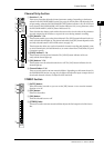
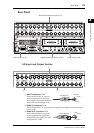
Rear Panel
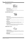
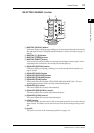
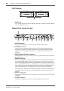
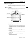
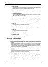
AD Input and Output Section
A INPUT connectors 1–16
These balanced XLR-3-31-type con-
nectors accept line-level and micro-
phone signals. The nominal signal level
ranges from –60 dB through +4 dB.
B OMNI IN connectors 1–4
These balanced XLR-3-31-type connectors accept line-level signals. The nominal signal
level is +4 dB.
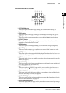
C OMNI OUT connectors 1–4
These balanced XLR-3-32-type con-
nectors output any Bus signals and
channel Direct Out signals. The nomi-
nal signal level is +4 dB.
WORD CLOCK
INOUT
CONTROL
INOUT
TO HOST
USB
REMOTE MIDI
SMPTE IN
COAXIAL AES/EBUCOAXIALAES/EBU
2
2
1
2TR IN
DIGITAL
METER
1
SLOT
SLOT
INPUT
OMNI
IN
23456781101112131415 9
23456781101112 9
213
16
4
AC IN
POWER
ON
OFF
AD Input and Output Section (p. 25)
Power Section (p. 27) Digital I/O & Control Section (p. 26) SLOT Section (p. 26)
INPUT
OMNI
IN
23456781101112131415 9
23456781101112 9
213
16
4
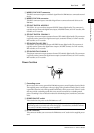
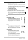
1
2 3
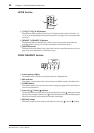
Male XLR plug
1 (ground)
2 (hot)
3 (cold)
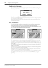
Female XLR plug
1 (ground)
2 (hot)
3 (cold)