50 Chapter 4—Connections and Setup
DM1000 Version 2—Owner’s Manual
• 2D2L & 2D2R ...............2TR DIGITAL IN 2 (L/R)
• BUS1–8.......................... Bus 1–8 Outputs
• AUX1–8......................... Aux Send 1–8 Outputs
2 Use the cursor buttons to move the cursor to a patch parameter (
1) for
which you want to change the assignment, and rotate the Parameter wheel
or press the [INC]/[DEC] buttons to modify the patching.
3 Press [ENTER] to confirm the change.
Patching Omni Outs
By default, the Omni Outs are patched as follows:
• OMNI OUT connectors 1–8 ..............Aux Sends 1–8
• OMNI OUT connectors 9–10 ............Stereo Bus L & R
• OMNI OUT connectors 11–12..........Control Room Monitor L & R
Follow the steps below to view or change the patching.
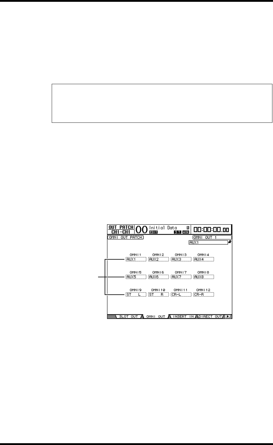
1 Press the DISPLAY ACCESS [OUTPUT PATCH] button repeatedly until the fol-
lowing page appears.
Signals that are currently assigned to the OMNI OUT connectors are shown in the param-
eter boxes (
1) underneath the connector numbers. The parameter indicators are
explained below:
• – .............................................................No assignment
• BUS1–BUS8..........................................Bus 1–8 signals
• AUX1–AUX8 ........................................Aux Send 1–8 Signals
• ST L/R....................................................Stereo Bus signals
• INS CH1–INS CH48 ...........................Input Channels 1–48 Insert Outs
• INS BUS1–INS BUS8 ..........................Bus 1–8 Insert Outs
• INS AUX1–INS AUX8.........................Aux Send 1–8 Insert Outs
• INS ST-L/ST-R......................................Stereo Bus Insert Outs
Tip:
•By default, you can also use the Encoders to select Input Channel sources. Rotate the Encoders
to display the In Patch/In Patch page and select sources. Press the Encoder push switches to
confirm the changes.
•To restore the default patching, recall Input Patch memory #00 (see page 176).
1


