


Control Room Monitoring 119
DM1000 Version 2—Owner’s Manual
Control Room Monitoring
10
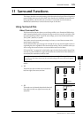
10 Control Room Monitoring
This chapter explains how to set up control room monitoring and use the Solo and Talkback
functions on the DM1000.
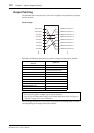
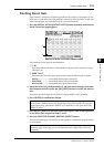
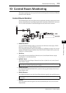
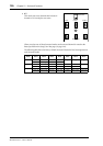
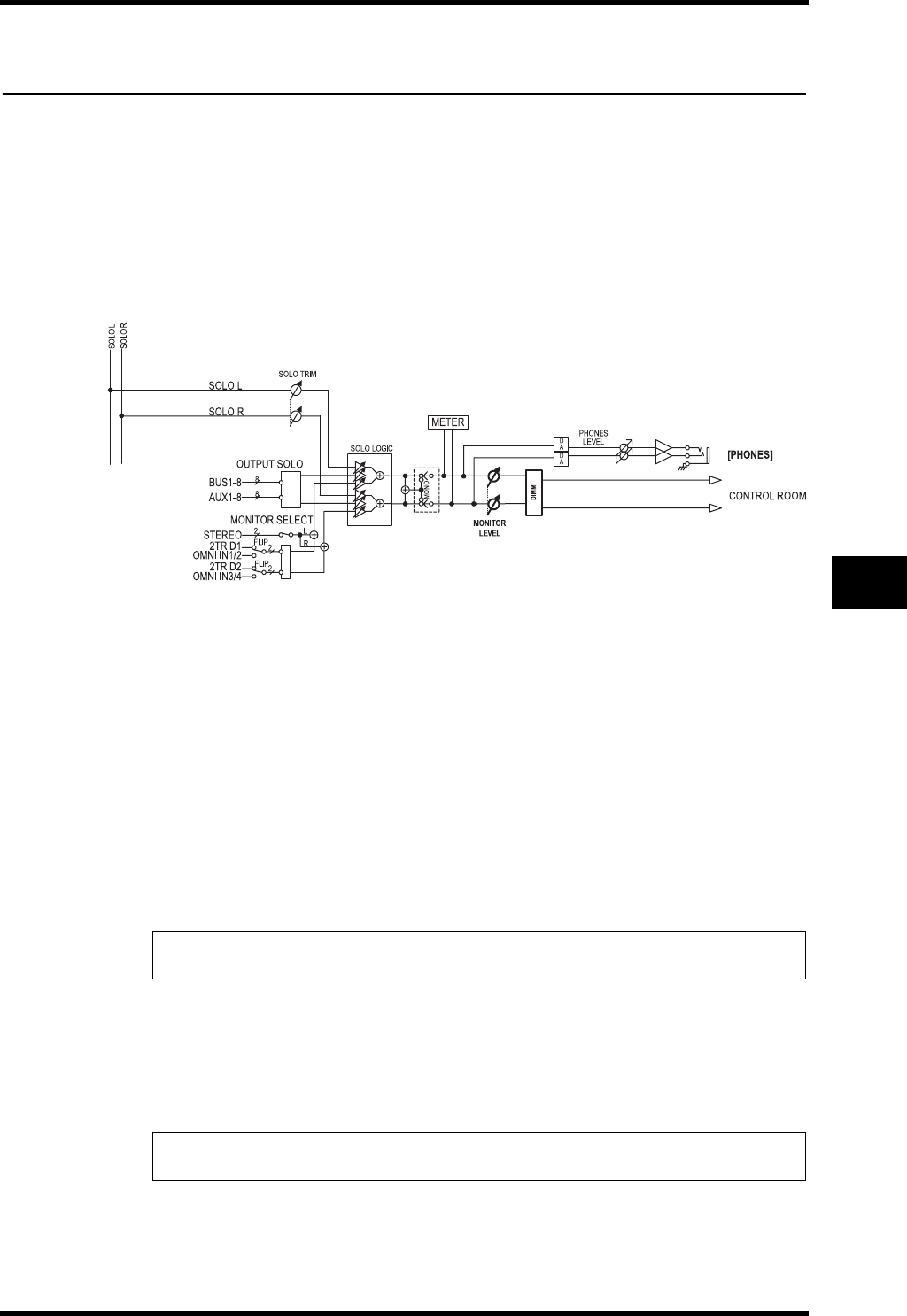
Control Room Monitor
The DM1000 features the Control Room stereo signal path to feed the control room’s main
monitors. By default, the Control Room signal source is patched to OMNI OUT connectors
11 & 12, which can feed the Control Room signal to the control room’s monitor.
• MONITOR SELECT
As a Control Room Monitor signal, you can select one from Stereo Out output, 2TR IN
DIGITAL 1 input, and 2TR IN DIGITAL 2 input.
If you change the parameter setting on the Monitor | C-R/TB page (see page 122), you can
monitor the OMNI IN signal, instead of the 2TR IN DIGITAL signal, when you press the
[2TR D1] or [2TR D2] button.
• SOLO bus
This special bus routes soloed Input Channels to the Control Room Monitor output,
bypassing Bus 1–8 and the Stereo Bus.
• OUTPUT SOLO
This section routes soloed Output Channels (Aux Out 1–8, Bus Out 1–8) to the Control
Room Monitor output.
• MONITOR LEVEL
Use the MONITOR [MONITOR LEVEL] control on the top panel to adjust the Control
Room Monitor level.
• DIMM (Dimmer)
The [DIMMER] button lowers the Control Room Monitor signal by the specified amount.
• PHONES
The Control Room Monitor signal is also fed to the PHONES jack. You can set the level
independently.
Note: Input and Output Channels cannot be solo-monitored simultaneously. The solo func-
tion for the most-recently soloed channels is enabled.
Note: The Dimmer function is activated automatically when the Talkback or Oscillator func-
tion is active.