


Setting the Input Channels from the Display 65
DM1000 Version 2—Owner’s Manual
6
Input Channels
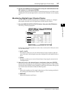
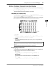
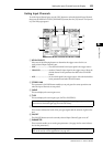
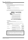
Gating Input Channels
To set the Input Channel gates, use the [SEL] buttons to select the desired Input Channel,
then press the DISPLAY ACCESS [DYNAMICS] button, then the [F1] button. The Dynam-
ics | Gate Edit page appears.
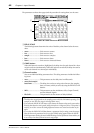
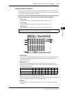
A KEYIN SOURCE
Select one of the following buttons to determine the trigger source for the cur-
rently-selected Input Channel’s gate.
• SELF...............................The selected channel’s own input signal is the trigger source.
• CHANNEL ....................Another Channel’s input signal is the trigger source. Select the
desired channel in the parameter box below the CHANNEL
button.
• AUX ................................An Aux Send signal is the trigger source. Select the desired bus
in the parameter box below the AUX button.
B STEREO LINK
This parameter’s ON/OFF button enables you to pair gates for stereo operation even
when the Input Channels are not paired.
C CURVE
This area displays the current gate curve.
D TYPE
This area displays the current gate type (GATE or DUCKING).
E Meters
These meters indicate the levels of the post-gate signals and the amount of gain reduc-
tion.
F ON/OFF
The ON/OFF button turns the currently-selected Input Channel’s gate on or off.
G PARAMETER
These controls enable you to set the gate parameters. (See page 324 for more informa-
tion on the parameters.)
Note: Yo u cannot change the gate type on this page. To change the gate type, recall a pro-
gram that uses the desired gate type from the Gate library.
Tip: You can store the gate settings in the Gate library, which features preset programs
that can be used for various applications (see page 181).
4
5
7
6
1
3
2