


Wordclock Connections and Settings 47
DM1000 Version 2—Owner’s Manual
4
Connections and Setup
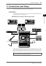
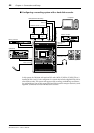
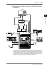
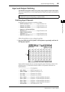
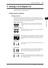
If the external devices do not have wordclock in and out connectors, you can use the clock
information included in the digital audio signals. In this case, digital audio signals and
wordclock signals are transferred via the 2TR OUT DIGITAL and 2TR IN DIGITAL jacks
or via the digital I/O cards installed in the rear panel slots.
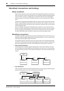
Specifying the Wordclock Source
To digitally connect the DM1000 to external devices, you must specify the wordclock source
for the system. Follow the steps below.
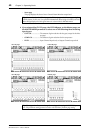
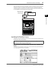
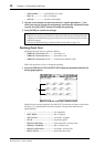
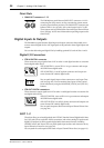
1 Press the DISPLAY ACCESS [DIO] button, then press the [F1] (WORD CLOCK)
button.
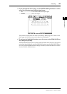
The Word Clock page appears. On this page, you can view the current synchronization sta-
tus of input signals at each slot and connector.
Note: When you change the wordclock settings on any device in your digital audio system,
some devices may output noise due to being out of synchronization. Be sure to turn down your
monitoring device before changing wordclock settings.
AUXPAN
DISPLAY
ASSIGN
ENCODER MODE
EQUALIZER
LOW
HIGH
GAIN
Q
FREQUENCY
LOW MID
HIGH MID
ROUTING
12
34
56
78
STEREO DIRECT
DISPLAY
DISPLAY
SELECTED CHANNEL
16
BUS 8
32 48
15
BUS 7
31 47
14
BUS 6
30 46
13
BUS 5
29 45
12
BUS 4
28 44
11
BUS 3
27 43
10
16151413121110
20dB
ONOFF
+48V
1
2
3
4
5
6
78 1213 14 15
16
91011
1615141312111098765432
PEAK
SIGNAL
1
-16
-60
GAIN
-16
-60
GAIN
-16
-60
GAIN
-16
-60
GAIN
-16
-60
GAIN
-16
-60
GAIN
-16
-60
GAIN
-16
-60
GAIN
-16
-60
GAIN
-16
-60
GAIN
-16
-60
GAIN
-16
-60
GAIN
-16
-60
GAIN
-16
-60
GAIN
-16
-60
GAIN
-16
-60
GAIN
PEAK
SIGNAL
PEAK
SIGNAL
PEAK
SIGNAL
PEAK
SIGNAL
PEAK
SIGNAL
PEAK
SIGNAL
PEAK
SIGNAL
PEAK
SIGNAL
PEAK
SIGNAL
PEAK
SIGNAL
PEAK
SIGNAL
PEAK
SIGNAL
PEAK
SIGNAL
PEAK
SIGNAL
PEAK
SIGNAL
PAD
20dB 20dB 20dB 20dB 20dB 20dB 20dB 20dB 20dB 20dB 20dB 20dB 20dB 20dB 20dB
ONOFF
+48V
ONOFF
+48V
ONOFF
+48V
ONOFF
+48V
ONOFF
+48V
ONOFF
+48V
ONOFF
+48V
ONOFF
+48V
ONOFF
+48V
ONOFF
+48V
ONOFF
+48V
ONOFF
+48V
ONOFF
+48V
ONOFF
+48V
ONOFF
+48V
0
5
10
15
20
30
40
50
60
70
50
40
30
20
15
10
+10
5
0
5
ON
SOLO
SEL
AUX 1
1
1
17 33
0
5
10
15
20
30
40
50
60
70
50
40
30
20
15
10
+10
5
0
5
ON
SOLO
SEL
AUX 2
2
2
18 34
0
5
10
15
20
30
40
50
60
70
50
40
30
20
15
10
+10
5
0
5
ON
SOLO
SEL
AUX 3
3
3
19 35
0
5
10
15
20
30
40
50
60
70
50
40
30
20
15
10
+10
5
0
5
ON
SOLO
SEL
AUX 4
4
4
20 36
0
5
10
15
20
30
40
50
60
70
50
40
30
20
15
10
+10
5
0
5
ON
SOLO
SEL
AUX 5
5
5
21 37
0
5
10
15
20
30
40
50
60
70
50
40
30
20
15
10
+10
5
0
5
ON
SOLO
SEL
AUX 6
6
6
22 38
0
5
10
15
20
30
40
50
60
70
50
40
30
20
15
10
+10
5
0
5
ON
SOLO
SEL
AUX 7
7
7
23 39
0
5
10
15
20
30
40
50
60
70
50
40
30
20
15
10
+10
5
0
5
ON
SOLO
SEL
AUX 8
8
8
24 40
0
5
10
15
20
30
40
50
60
70
50
40
30
20
15
10
+10
5
0
5
ON
SOLO
SEL
BUS 1
9
9
25 41
0
5
10
15
20
30
40
50
60
70
50
40
30
20
15
10
+10
5
0
5
ON
SOLO
SEL
0
5
10
15
20
30
40
50
60
70
50
40
30
20
15
10
+10
5
0
5
0
5
10
15
20
30
40
50
60
70
50
40
30
20
15
10
+10
5
0
5
0
5
10
15
20
30
40
50
60
70
50
40
30
20
15
10
+10
5
0
5
0
5
10
15
20
30
40
50
60
70
50
40
30
20
15
10
+10
5
0
5
0
5
10
15
20
30
40
50
60
70
50
40
30
20
15
10
+10
5
0
5
0
5
10
15
20
30
40
50
60
70
50
40
30
20
15
10
+10
5
0
5
ON
SOLO
SEL
ON
SOLO
SEL
ON
SOLO
SEL
ON
SOLO
SEL
ON
SOLO
SEL
ON
SOLO
SEL
BUS 2
26 42
AUTO
ON
SEL
STEREO
70
60
50
40
30
20
15
10
5
0
AUX2 AUX3 AUX4
AUX6AUX 5 AUX7 AUX8
AUXSELECT
DISPLAY
AUX1
FADER MODE
FADER
AUX
DISPLAY ACCESS
AUTOMIX DIO SETUP UTILITY
MIDI REMOTE METER VIEW
PAIR /GROUP
INPUT
OUTPUT
EFFECTSURROUND DYNAMICS SCENE
/
PAN/
INSERT/DELAY
PATCH
PATCH
GRAB
SCENE MEMORY
STORE RECALL
DISPLAY
USER DEFINED
KEYS
ENTER
INC
DEC
TALKBACK LEVEL
PHONES
LEVEL
010
010
PHONES
MONITOR
LEVEL
SOLO CLEAR
2TR D1
2TR D2
DIMMER
TALKBACK
MONITOR
STEREO
SLOT
BUS
DISPLAY
100
F1 F2 F3
F4
0
OVER
-2
-4
-6
-8
-10
-12
-14
-18
-24
-30
-36
-42
-48
-56
-72
0
OVER
-2
-4
-6
-8
-10
-12
-14
-18
-24
-30
-36
-42
-48
-56
-72
LR
Digital I/O
card
External device
Digital audio signal
+
Wordclock signal