


Analog I/O & Digital I/O 53
DM1000 Version 2—Owner’s Manual
5
Analog I/O & Digital I/O
5 Analog I/O & Digital I/O
This chapter describes the DM1000’s analog and digital input/output connectors as well as
the basic operations involving the digital I/Os.
Analog Inputs & Outputs
AD Input Section
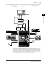
The DM1000’s rear panel features Input connectors 1–16, which enable you to connect
microphone and line-level sources, and OMNI IN connectors, which enable you to connect
line-level sources. Signals input at these connectors can be patched to Input Channels. (See
page 109 for more information on patching Input Channels.)
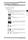
• INPUT connectors 1–16
These balanced XLR-3-31-type connectors accept line-level and
microphone signals. The nominal input range is –60 dB through
+4 dB.
• OMNI IN connectors 1–4
These balanced XLR-3-31-type connectors accept line-level signals.
The nominal signal level is +4 dB.
• Phantom Power
Inputs 1 through 16 feature switchable +48V phantom powering for
use with condenser-type microphones and direct boxes. Individual
+48V [ON/OFF] switches on each input turn phantom power on
and off.
•PAD switches
Inputs 1 through 16 feature pad switches, which attenuate input sig-
nals by 20 dB.
• GAIN controls
Inputs 1 through 16 feature rotary gain controls that adjust input
sensitivity. Input sensitivity ranges from +4 dB to –40 dB when the
Pad is on, and from –16 dB to –60 dB when the Pad is off.
• PEAK & SIGNAL Indicators
The SIGNAL indicator lights up when the input signal level is 20 dB
below nominal. The PEAK indicator lights up when the input signal
level is 3 dB below clipping.
INPUT
89
OMNI
IN
23
ONOFF
+48V
1
20dB
1
PAD
-16
-60
GAIN
PEAK
SIGNAL