


Setting the Input Channels from the Display 71
DM1000 Version 2—Owner’s Manual
6
Input Channels
Routing Input Channels
You can route each Input Channel to the Stereo Bus, Bus 1–8, or its own Direct Out. With
the default setting, signals are routed only to the Stereo Bus. However, you can patch signals
to a single or multiple destinations, if necessary.
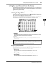
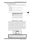
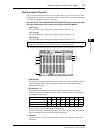
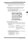
1 Press the SELECTED CHANNEL ROUTING [DISPLAY] button repeatedly until
the page listed below that contains the desired channels appears.
- CH1-16 page
This page enables you to change the routing for Input Channels 1–16.
- CH17-32 page
This page enables you to change the routing for Input Channels 17–32.
- CH33-48 page
This page enables you to change the routing for Input Channels 33–48.
The parameters on these three pages (and the procedure for setting them) are the same.
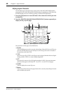
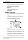
A PAN buttons
These buttons determine whether the Input Channel’s Pan setting is applied to the Bus
Outs. In surround mode, they also determine whether the Surround Pan setting is
applied to the Bus Outs.
B Bus buttons 1–8
These buttons route the currently-selected Input Channel to the Bus Outs. If the
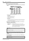
DM1000 is in Surround mode, the button indicators change as follows, depending on
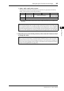
the selected Surround mode:
L=Left, R=Right, C=Center, S=Surround, Ls=Left Surround
Rs=Right Surround, E=Low Frequency Effect, Bs=Back Surround
The above table shows the default assignment. The actual assignment may vary, depend-
ing on the settings on the Setup | Surround Bus Setup page.
C S button
When this button is turned on, the currently-selected Input Channel is routed to the
Stereo Bus.
Tip: You can also display the desired page by pressing the ROUTING [DISPLAY] button once,
then press the [SEL] button or move the fader of the corresponding channel.
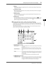
Bus buttons 12345678
Surround mode: 3-1
LRCS5678
Surround mode: 5.1
LRLsRs C E 7 8
Surround mode: 6.1
LRLsRs C Bs E 8
5
6
7
1
3
4
2
8