


284 Chapter 20—Other Functions
DM1000 Version 2—Owner’s Manual
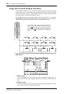
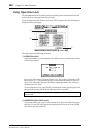
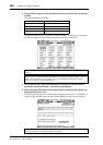
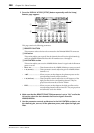
4 Assign the Bus signals to the slot channels that are used for the cascade con-
nection.
The following signals are available:
The following display page is an example of integrating Bus 1–8, Aux Send 1–4, Stereo Bus,
and Solo Bus signals via two 8-channel digital I/O cards (such as MY8-AT).
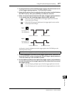
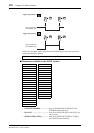
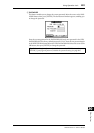
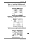
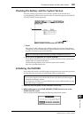
5 On the master unit, press the DISPLAY ACCESS [INPUT PATCH] button
repeatedly until the In Patch | Cascade In page appears.
6 Select the Input Channels on the master unit to which the Bus signals are
input from the Slave unit.
The following display page is an example of receiving the slave unit’s Bus 1–8, Aux Send 1–4,
Stereo Bus, and Solo Bus signals via two 8-channel digital I/O cards (such as MY8-AT).
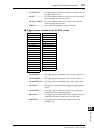
Options Description
CAS BUS1–BUS8
Bus 1–8 Cascade Outs
CAS AUX1–AUX8
Aux Bus 1–8 Cascade Outs
CAS ST-L, CAS ST-R
Stereo Bus L & R Cascade Outs
CASSOLOL, CASSOLOR
Solo Bus L & R Cascade Outs
Tip: Patching may vary depending on the type and number of buses used for the cascade con-
nection.
Note: Since the number of channels available on the digital I/O cards is limited, only Aux
Sends 1–4 are cascaded in this example. Using a 16-channel digital I/O card (such as
MY16-AT) enables you to cascade all buses.
Note: Be sure to patch the slave Bus signals to the same Buses on the master unit. Incorrect
patching will result in an incorrect cascade connection.